Download
1 / 35
350 likes | 681 Views
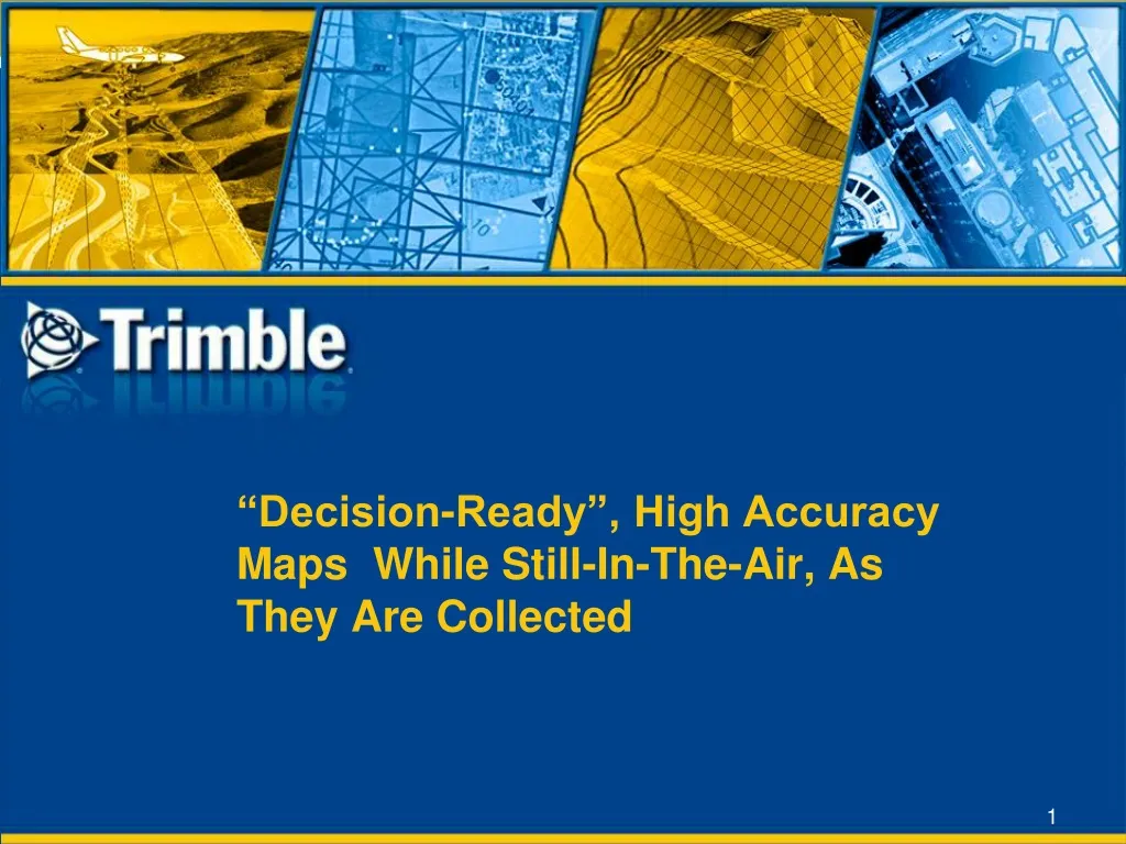
“Decision-Ready”, High Accuracy Maps While Still-In-The-Air, As They Are Collected. Ultra-Fast Mapping: Why? When?. Natural disasters require immediate response to save lives and property to survey damage to identify open access routes Security emergencies

E N D
“Decision-Ready”, High Accuracy Maps While Still-In-The-Air, As They Are Collected
Ultra-Fast Mapping: Why? When? • Natural disasters require immediate response • to save lives and property • to survey damage • to identify open access routes • Security emergencies • Decision ready imagery needed INSTANTLY to plan and execute response
Challenges • Large aircraft (or satellites) must fly high to capture images, the cloud deck often impedes image capture • Ortho-processing many small images using traditional Aerial Triangulation (AT) process is time consuming • AT requires good quality ground control information, which is very difficult to collect in unstable post-crisis areas • Large format cameras can’t efficiently collect data of small/irregular areas
Solution • Smaller aircraft and medium-format cameras are ideal • Direct Georeferencing • In-FlightOrtho software • produces full resolution orthorectified imagery in the aircraft as it is captured. Images are automatically developed, corrected and orthorectified
Trimble Digital Sensor System (DSS) 500 with In-FlightOrthoTM
Trimble DSS 500 Industry’s First Aerial Imaging Solution with “In-Air” Orthophoto Production
Trimble DSS 500Much more than “just a camera” • DSS is a directly-georeferenced, medium-format imaging solution • DSS includes a completely integrated, ready-to-use workflowwith IMU, flight management, metric imaging camera, software, and support/maintenance for all components • Every DSS includes In-Flight Ortho and RapidOrtho for ultra fast orthophoto production
DSS 500: Dramatically New • The DSS 500 with In-FlightOrtho is the next generation of DSS solutions, comprised of: • All-new compact camera system with embedded computer, solid-state drives, Applanix POSTrack V6 • 7” Pilot smart display • 8.9” Operator tablet (not required for pilot only operation) • Azimuth mount or optional 3-axis SSM 270 mount • Various camera and lens • options, 39 MP/80 MP • RGB or CIR or NIR • “In-Air” image production
In-FlightOrtho™: Only with DSS • Every DSS has what no other system has – the ability to produce directly georeferenced orthos in real-time, in the air. • Real-time image and ortho thumbnail display
In-FlightOrtho™ (comes included on all systems) • Real-time image & ortho thumbnail display • Instantly detect issues with imagery and georeferencing: “Air-to-ground QC” • No special computer HW required; off-the-shelf laptop with SSD and Ethernet cable • Absolute accuracy limited by DEM accuracy and source of GNSS corrections • Sub-meter accuracy possible with Omnistar XP
Why DSS 500? • Every DSS Includes In-FlightOrtho and RapidOrtho • Ideal for rapid, high-accuracy mapping • Direct georeferencing • computes position of points on ground without GCP – no Aerial Triangulation (AT) required • Mapping grade camera • calibrated, stable over time • Process certified by the USGS
Why DSS 500? continued • Flexibility of variable focal lengths • Radiometric accuracy • Complete turnkey solution including: • all hardware and software • Workflow • Installation • Training • warranty and support
Direct Georeferencing • Measures position and orientation using Navigation Sensors • Computes position of points on ground without needing GCPs Ideal for medium-format digital camera where traditional AT can often be difficult & costly due to large number of images & GCPs required
Direct Georeferencing continued • Orthophoto production can be completed in hours; not months / weeks / days • Saves cost and reduces the risk of placing personnel in dangerous environments to collect GCPs • With In-FlightOrtho direct georeferencing can be obtained on the fly
Advantages • Low cost to operate • state-of-the-art computer hardware is extremely compact, low-power • can be easily deployed in small, low-cost-to-operate aircraft for very cost-effective mapping • proven pilot-only operation, reducing personnel and fuel costs • Platform for future business growth • Designed to scale to support future OTS computing hardware, reducing your future upgrade costs • Supports other sensors, so you can grow as your business grows
Advantages Continued • Directly Georeferenced Imagery • DSS is designed and built around the use of Applanix POS AV Direct Georeferencing for maximum productivity and accuracy • Super Efficient Flight Management System • With an embedded POSTrack flight management system with full DEM support, the DSS is capable of taking each and every image at exactly the right location and overlap
Advantages Continued • “Air-to-Ground” Quality Control • The ultimate in-field Quality Control through In-FlightOrtho capability • Full-res orthophotos are produced in real-time immediately upon image capture using the GNSS-Inertial solution and onboard DEM • The pilot / operator can see at a glance how things look and fit together “on-the-ground”, immediately verify the quality of the imagery, GNSS data, Inertial data and camera interior orientation. • If a problem is spotted the mission can be immediately aborted, or images re-flown. • Benefit: massive potential cost savings in flight & ground costs
Who uses the DSS? • Government mapping agencies • Civil and defense applications • Small and medium-sized mapping companies • Corridors, small / irregular collects, low-altitude (under cloud) • Combined with LIDAR • Smaller aircraft = dramatically lower operating costs • Larger mapping companies • Same small / irregular projects, seen as complementary to large-format camera systems (reduces cost on small projects)
DSS 500 Product Lineup • DSS camera options • 539 (39MP sensor) • 580 (80MP sensor) • DSS system options • DSS Tactical Lenses • DSS SingleCam • DSS DualCam • DSS Azimuth mount • DSS 3-axis gyro-stabilized mount • DSS software options: • DSS In-FlightOrtho • DSS In-FlightOrtho High Precision Option, with Inpho OrthoBox & DTMBox
Digital Sensor System Options • DSS In-FlightOrthoTM • Real-time, mapping-grade ortho-mosaics • High-productivity ortho mapping • DSS Tactical In-FlightOrthoTM • Real-time, high-resolution ortho maps from safe flying heights
Digital Sensor System Optionscontinued • DSS RapidOrthoTM • Ultra-fast, mapping-grade ortho-mosaics • High-productivity ortho and stereo mapping • DSS DualCam • Complete solution with two camera heads for either simultaneous 4 band orthos (RGB + NIR) or wide swath RGB capture
Tactical Option: high-res images from safe flying heights • 210 & 240mm lens options • High resolution images from > 10000 feet: sub-10cm centimeter-scale GSDs • Previous generation DSS 400 deployed in Afghanistan and Iraq • high accuracy of geocoding, high-resolution of imagery proved to be invaluable for threat assessment • Net result: produce high resolution map from higher altitudes for recon mapping applications • Available with In-FlightOrtho 8 cm GSD @ 10000’ AGL, DSS VIS image
Crop of full image, 9cm GSD from 10,500’ AGL. DSS 439 with 250 mm lens.
picture (close up) of a DSS 539 210 mm lens or DSS 580 240 mm lens
DSS DualCam • Standard DSS 539/580 system expanded to add 2nd nadir camera configured for VIS/NIR • Allows: • simultaneous collection of VIS and NIR imagery for mapping and remote sensing applications (DSS 539) • Or collection of wide swath VIS imagery (DSS 539/580) • Allows high-productivity in a single flight
DSS DualCam continued • All hardware modules, camera heads, and workflow software of DualCam compatible with standard DSS 539/580 • Provides 100% interchangeability of modules for support and flexible re-configuration
DSS DualCam Sensor Head • Form and fit of camera heads identical to standard DSS 539/580 • Mounted in small-footprint SSM 270 stabilized mount, automatically leveled and steered by POSTrack • 100% flexibility for support and camera angle re-configuration
DualCam – 4 Band Orthophoto Option • Orthophotos produced individually for the RGB and NIR cameras • These are then co-registered and output with following options: • Two separate orthophotos (RGB/NIR) • Single 4 band orthophoto (RGB/NIR) • Four separate Grayscale orthophotos (R/G/B/NIR) • Single CIR orthophoto (NIRRG) • Orthophotos can then be mosaicked as needed using OrthoVista
DualCam – 4 Band Orthophoto Option continued • RGB • NIR • 4 Band
DualCam – Wide Swath • Add a 2nd VIS camera to nearly double swath width Need an image
Products and Specifications – DSS539 and DSS580 Orthophotos / orthomosaic: Typical RMSE ground accuracy = 1.2 X pixel resolution (e.g. 0.12m RMS at 0.10m GSD) Digital Elevation Model from stereo: Typical RMSE vertical accuracy = 3 X pixel resolution (e.g. 0.9m RMS at 0.3m GSD) 3 cm GSD. DSS image courtesy of Tuck Mapping.