Download
1 / 32
840 likes | 3.32k Views
AUTOMATIC FLIGHT CONTROL SYSTEM (AFCS). Presented by. PURPOSE: To develop the Student Instructor Pilot’s understanding of the Automatic Flight Control System NEED: You will be instructing this subject in the near future. TOPICS OF DISCUSSION. Auto Flight Control System

E N D
AUTOMATIC FLIGHT CONTROL SYSTEM(AFCS) Presented by
PURPOSE: To develop the Student Instructor Pilot’s understanding of the Automatic Flight Control System • NEED: You will be instructing this subject in the near future
TOPICS OF DISCUSSION • Auto Flight Control System • What is Stability? • Stability Augmentation System • TRIM • Flight Path Stabilization • Malfunction Analysis
WHAT IS AFCS? • AFCS enhances the stability and handling qualities of the UH60 helicopter. It is comprised of four subsystems: • Stability Augmentation System (SAS) • Trim Systems • Flight Path Stabilization (FPS) • Stabilator (previously discussed)
Stability, in physics and engineering, the property of a body that causes it to return to its original position or motion as a result of the action of the so-called restoring forces, or torques, once the body has been disturbed from a condition of equilibrium or steady motion.
STABILITY AUGMENTATION SYSTEM (SAS) • Purpose: Provide dynamic stability through short term rate dampening in the pitch, roll, and yaw axis. • SAS systems: SAS 1 & SAS 2 • Control Authority: Each SAS has 5% control authority, for a total of 10%
SAS 1 • Components: • SAS1 amplifier (analog) is located in the avionics compartment • Three SAS actuators • Input Signals: • Pitch - rate gyro in the #1 stabilator amplifier • Roll - pilot’s (number 2) vertical gyro • Yaw - yaw rate gyro in the SAS1 amplifier • additional signals - #1 filtered lateral accelerometer, airspeed transducer
#1 pitch rate gyro #2 vertical gyro #1 lateral accl a/s transducer Yaw gyro
SAS 2 • Components: • SAS2 is the SAS/FPS computer (digital) • Three SAS actuators • Input Signals: • Pitch - rate gyro in the #2 stabilator amplifier • Roll - roll rate gyro in the avionics compartment • Yaw - yaw rate gyro in the avionics compartment
SAS 2 • Additional Signals • #1 & #2 filtered lateral accelerometer • rate gyro in the #1 Stabilator amplifier • air data transducer
#2 pitch rate gyro Roll rate gyro Yaw rate gyro #1 & #2 lateral accl Air data transducer
TRIM SYSTEM • Purpose: Provide a gradient force, maintains position of the cyclic and tail rotor controls • Components: • two electromechanical actuators, and one electrohydromechanical actuator • TRIM REL switch on the cyclic, and pedal micro switches on the directional control pedals • monitored by the SAS/FPS computer
TRIM SYSTEM • Slip Clutches • both the roll and yaw trim actuators incorporate slip clutches to allow the pilots to make control inputs should either actuator jam • 13 pounds maximum in the roll • 80 pounds maximum in the yaw
Airspeed transducer #1 collective position sensors
FLIGHT PATH STABILIZATION • Purpose: Enhances static stability through long term rate dampening in the pitch, roll, and yaw axis. • Components: SAS/FPS computer, and three trim actuators • Control Authority: When coupled with trim, 100% control authority
FLIGHT PATH STABILIZATION • The following systems must be on and operational for FPS to function 100% • SAS 1 and/or SAS 2 • Boost • Trim • Stabilator in AUTO mode enhances FPS operation, but is not required
FLIGHT PATH STABILIZATION FPS provides the following functions: BELOW 60 KIAS ABOVE Attitude Hold/ Airspeed Hold Pitch Axis Attitude Hold Attitude Hold Roll Axis Attitude Hold Heading Hold or Turn Coordination Heading Hold Yaw Axis
#1 pitch rate gyro #1 vertical gyro #1 vertical gyro ASN 43 #1 lateral accl Airspeed transducer #1 collective position sensor Airspeed transducer #1 collective position sensor
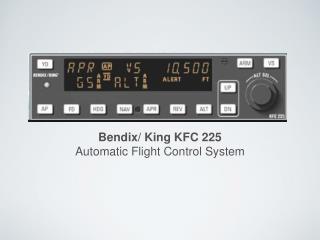
AUTO FLIGHT CONTROL SAS 1 SAS 2 TRIM FPS ON ON ON ON BOOST ADVISORY FAILURE RESET RESET ON ON POWER ON RESET
9.29.1 SAS Failure With No Failure/Advisory Indication. SAS 1 switch - Off. If condition persists: SAS 1 switch - On. SAS 2 switch - Off. If malfunction still persists: SAS 1 and FPS switchs - Off.
AUTO FLIGHT CONTROL SAS 1 SAS 2 TRIM FPS ON ON ON ON BOOST ADVISORY FAILURE RESET RESET SAS2 ON ON POWER ON RESET
9.29.2 SAS2 Failure Advisory Light On. Power On Reset switches - Simultaneously press and then release.
SAS OFF AUTO FLIGHT CONTROL SAS 1 SAS 2 TRIM FPS ON ON ON ON BOOST ADVISORY FAILURE RESET RESET ON ON POWER ON RESET
9.29.3 SAS OFF Caution Light On. FPS switch - Off.
SAS OFF AUTO FLIGHT CONTROL SAS 1 SAS 2 TRIM FPS ON ON ON ON BOOST ADVISORY FAILURE RESET RESET ON ON POWER ON RESET
FLT PATH STAB AUTO FLIGHT CONTROL SAS 1 SAS 2 TRIM FPS ON ON ON ON BOOST ADVISORY FAILURE RESET RESET ON ON A /S POWER ON RESET
9.29.4 FLT PATH STAB Caution Light On. POWER ON RESET switches - Simultaneously press and then release. WARNING If the airspeed fault advisory light is illuminated, continued flight above 70 KIAS with the stabilator in the AUTO MODE is unsafe since a loss of the airspeed signal from the remaining airspeed sensor would result in the stabilator slewing full down.
9.29.5 Pitch, Roll or Yaw/Trim Hardover. POWER ON RESET switches - Simultaneously press and then release. If failure returns, control affected axis manually.
9.29.6 Trim Actuator Jammed. LAND AS SOON AS PRACTICABLE.