Download
1 / 20
200 likes | 223 Views
SYSTEM MODELING AND ANALYSIS. BASIC ELEMENTS OF MECHANICAL SYSTEMS In general, vibrating systems have potential and kinetic energy storage elements. If the system includes damping, there is also energy absorbing elements. The basic relations for these elements are given below.

E N D
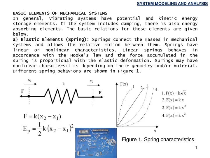
SYSTEM MODELING AND ANALYSIS BASIC ELEMENTS OF MECHANICAL SYSTEMS In general, vibrating systems have potential and kinetic energy storage elements. If the system includes damping, there is also energy absorbing elements. The basic relations for these elements are given below. a) Elastic Elements (Spring): Springs connect the masses in mechanical systems and allows the relative motion between them. Springs have linear or nonlinear characteristics. Linear springs behaves in accordance with the Hooke’s law and the force accumulated in the spring is proportional with the elastic deformation. Springs may have nonlinear charactersitics depending on their geometry and/or material. Different spring behaviors are shown in Figure 1. Figure 1. Spring characteristics
SYSTEM MODELING AND ANALYSIS m, I ω T b) Inertia Elements: Inertia elements store the kinetic energy. Inertia elements can make translational and rotational motion. They also make translational and rotational motion at the same time. Basic relations for inertia elements are given below. Translational Rotational I: Mass moment of inertia (Moment)
SYSTEM MODELING AND ANALYSIS c) Damping Elements: Damping elements absorb the energy indamped systems. Dashpot type elements provide damping with fluid friction and decrease the vibration amplitudes in an exponential manner. In this element, mechanical energy is converted to heat energy. The element equation is given below. Orifice Energy loss Energy dissipation occurs during motion. So, reaction force is propotional with the velocity (not displacement)
SYSTEM MODELING AND ANALYSIS Homogeneous slender bars are freqeuntly used in vibrating mechanical sytems. This element can simply rotate about an axis placed on it or both rotates and translates in a plane. In rotational motion, the kinetic energy stored in the element is directly proportional with the inertia of the body. (Angular velocity) (mass) (length) (Mass per unit length)
SYSTEM MODELING AND ANALYSIS If the homogeneous slender beam rotates about the axis which passes through the point B, the mass moment of inertia about point B can be calculated using the parallel axis theorem (Steiner’s theorem). Mass moment of inertia about center of gravity Distance between the center of gravity and rotation axis Kinetic energy of the bar rotating about point B can be written as
SYSTEM MODELING AND ANALYSIS x k x R R LINEARIZATION OF VIBRATION PROBLEMS (SMALL DISPLACEMENTS) Vibration problems can be analysed by the solution of linear differential equations for small displacements and rotations. If the displacements and rotations are large, then the nonlinear forms of governing differential equations must be considered. Taylor-series expansion of sin is For small angular displacements <<1 Taylor-series expansion of cos is For small angular displacements <<1
SYSTEM MODELING AND ANALYSIS A xA O F(t) m x(t) g c k For small motions, the same relation between the angular and translational displacements is valid for a beam which rotates about an axis. OBTAINING THE GOVERNING EQUATIONS OF MOTION FOR A MECHANICAL SYSTEM The governing equations of motion of a mechanical system determines the dynamic response of the system under an external excitation (force or displacements) or predefined initial conditions. The equations of motion can be obtained using different methods. Commonly used methods are described below. • Newton’s 2nd Law: The mechanical system shown in the figure has one degree of freedom and the motion of mass m can be represented by coordinate x. As per the Newton’s 2nd law of motion, the sum of the forces acting on the mass m is equal to mass * acceleration of the mass.
SYSTEM MODELING AND ANALYSIS F(t) mg m x(t)=xs+xd(t) k(xs+xd) x(t) xs m Static equilibrium k xd(t) k Free Body Diagram xs: static displacement of m xd: dynamic displacement of m (about xs) Newton’s 2nd law for translational systems Newton’s 2nd law for rotational systems
SYSTEM MODELING AND ANALYSIS F(t) mg m x(t)=xs+xd(t) k(xs+xd) Displacement of m is the displacement about static equilibrium 2. Dynamic Equilibrium Method (d’Alembert Principle): In this method, inertia forces are placed in the FBD and the static equilibrium equations are applied. or
SYSTEM MODELING AND ANALYSIS d’Alembert or inertia force F(t) mg m x(t)=xs+xd(t) k(xs+xd) use x=xd
SYSTEM MODELING AND ANALYSIS Sum of the power given to the external systems Sum of the mechanical power given to the system 3. Energy Method : In this method, principle of conservation of the energy is applied. The rate of increase in the total energy of a system is equal to the power supplied to the system. Where, Et denotes the sum of potential and kinetic energies of the system, Pnet denotes the supplied net power; the sign of the power supplied by the external forces and moments is +, the power given to the external systems and heat power in the damping elements has negative (–) sign. Sum of the thermal power discharged from the damping element
SYSTEM MODELING AND ANALYSIS 4. Lagrange’s Method: In this method, potential and kinetic energy expressions of the system are written. Then, generalized forces are derived from the virtual work of external forces and damping forces. Finally, the Lagrange’s equation is used to obtain the equations of motion of the system. The Lagrangian of the system is the difference between the kinetic energy and potential energy Generalized Force
SYSTEM MODELING AND ANALYSIS O l g θ m Where qi denotes the ith generalized cordinate of the system. Qi denotes the generalized force acting on the ith generalized coordinate. Generalized force is obtained from the Wirtual Work expression. In general, kinetic energy is related with the velocity of the generalized coordinate and potential energy is related with the generalized coordinate, then the simple form of the Lagrange’s equation can be written as On the other hand, in some mechanical systems, kinetic energy may be a function of generalized coordinate. For this systems, 3rd term of Lagrange’s equation should be taken into account. Lagrange’s equation is a force equilibrium or a moment equilibrium for translational and rotational systems, respectively.
SYSTEM MODELING AND ANALYSIS The virtual works of external forces and damping forces on the generalized coordinates are considered in order to obtain the generalized forces. For this purpose, a small displacement () independent of time is applied to each generalized coordinate and the virtual works done by these forces are written as
SYSTEM MODELING AND ANALYSIS Example: Obtain the equation of motion for the single degree of freedom system shown in the figure. Equation of motion is :
SYSTEM MODELING AND ANALYSIS Example: Obtain the equations of motion for two-degree of freedom system shown in the figure. For multi degree of freedom systems, Lagrange’s equation is written for every generalized coordinate. Lagrange’s equation for x1 ,
SYSTEM MODELING AND ANALYSIS Lagrange’s equation for x2, If we write the equations of motion in matrix form For lineer systems, Mass, Damping and Stifness matrices are symmetric.
SYSTEM MODELING AND ANALYSIS Example: Obtain the equations of motion for two-degree of freedom system shown in the figure. h
SYSTEM MODELING AND ANALYSIS Lagrange’s equation for θ1, Lagrange’s equation for θ2,