Download
1 / 40
400 likes | 517 Views
BalloonWinds Integration Status. January 15, 2006 Ann Arbor, MI. BalloonWinds Overview/Goals. Validate instrument system models for a downward looking platform in a near space environment Demonstrate Multi-Order Photon Recycled Fringe Imaging from a high altitude (30 km) balloon

E N D
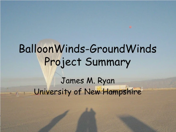
BalloonWinds Integration Status January 15, 2006 Ann Arbor, MI
BalloonWinds Overview/Goals • Validate instrument system models for a downward looking platform in a near space environment • Demonstrate Multi-Order Photon Recycled Fringe Imaging from a high altitude (30 km) balloon • Demonstrate technology under as many atmospheric conditions as possible; i.e. high and low clouds, high and low winds, variable boundary layer aerosol conditions, day and nighttime
Flight Schedule • Comments/ Notes • All balloon flights will include molecular and aerosol channel optimized interferometers • First 2 flights are intended to be concept demonstrations • Flight 1: Demonstrate the electrical, thermal, mechanical, and optical performance of the integrated instrument for nighttime flight conditions. • Flight 2: Demonstrate the ability to operate during the daytime given the additional thermal load and the increased optical background • Instrument modifications required for the final flight will be made in the 4 months leading up to the final flight.
Gondola Design • Gondola Mass: ~5000 lbs • Power Requirements: 1300 W • Thermal Management: Ice Phase Change, 0°C coolant temperature • Size: 8’ h x 8’w x 12’ l • 26-28 Lithium Ion Batteries
BalloonWinds Program Status at a Glance • Instrument system being delivered to UNH for gondola integration this week
Gondola Hardware Electronics Chamber -Thermal Chamber Gondola Frame
BalloonWinds Trailer • Trailer is 30’ long and 13’ tall • Door for trailer acts as ramp for gondola to be rolled into • Trailer contains office and all ground support equipment 8’ Office
Laser-Telescope Subsystem Laser GLTI Telescope • Laser Head & Control Electronics • Beam Delivery and Beam Steering • Independent telemetry data acquisition system for environmental monitoring and power control. • Liquid to air heat exchangers regulate internal temperature • Pressure maintained to 1.0 ATM • Telescope and laser coupled through common interface (GLTI)
BalloonWinds Telescope • Athermal design: 30 C to –55 c focal change <2 mm. • Rigid structure: Elevation change from +45 to –45 the pointing angle deviates 49 urad
Diode Pumped Laser • Laser is thermally controlled by forced convection • Electronics and optical head integrated as one unit
Diode Pumped Laser Frequency Stability • Histogram was derived from 1200 measurements • Results indicate a ~5MHz RMS laser frequency stability
Laser Enclosure Subsystem Beam Steering Assembly Heat Exchanger 2nd Beam Expander Assembly O-ring Seal Reference Fiber Pick-off Assembly Beam Delivery Window 1st Beam Expander Top Down View Beam Fold Mirror Connector Block FiberTek 355nm Laser Assembly
Laser Enclosure Subsystem Heat Exchanger Beam Steering Assembly 2nd Beam Expander Assembly O-ring Seal Reference Fiber Pick-off Assembly Beam Delivery Window 1st Beam Expander Top Down View Beam Fold Mirror Connector Block FiberTek 355nm Laser Assembly
Beam Delivery Optics in Laser Chamber Beam Delivery Plate
BalloonWinds Gondola/Instrument Concept Interferometer Chamber • Shock Mounted, Thermally Controlled Hermetic Vessel 20” ID x 44” • Molecular & Aerosol Interferometer Channels • Etalon Control Electronics • Narrow band Pre-Filter and associated optics • PMTs for telescope alignment and amplifiers • CCD Camera and Power Supply
Interferometer Part Identification Objective Lens Molecular Etalon Collimator Lens Aerosol Etalon Recycler Mount Fold Mirror Relay Lens Camera CLIO Exteder Filter Box
BalloonWinds Interferometer System with Flight Harnessing Fiber Harness Electrical Harnesses Cooling Lines
Molecular Interferometer System Recycler Face Fringe Spectrum Through Recycler Fiber Illumination Through Etalon Recycler Fiber Assembly
Molecular Interferometer System Fringe Spectrum Through Recycler Molecular Fringe Spectrum Through Full System Fringe Image Through Extender • Molecular Finesse = 5.7 • Recycling efficiency = 2.1 • #Orders = 4
Aerosol Fringe Image Full Optical System • Finesse= 6.87 • Recycling efficiency=2.3 • #Orders=12
First BalloonWinds Fringe Image Molecular Return Aerosol Return Laser Reference
Wrap-Up • What will be complete by next meeting…. • Full system integration • Side by side inter-comparison with GroundWinds NH • Thermal Vacuum testing of Gondola System • First Flight
ACKNOWLEDGEMENTS • The BalloonWinds team would like to thank the National Oceanic and Atmospheric Administration (NOAA) for their continued support of the GroundWinds and BalloonWinds fringe imaging technology.
Innovation & Results We are hiring! • Optical Engineers/Physicists • MS or PhD • Senior and entry level positions available • U.S. citizenship required