Download
1 / 9
90 likes | 167 Views
Barrel integration status. Jun 28 – 1 st module installed July 21 – all but 2 type 1 modules installed 1 cooling sleeve problem 1 HV problem (M1.35) Aug. 2 – type 1 complete Fixed cooling sleeve Gave up M1.35, use M1.26

E N D
Jun 28 – 1st module installed July 21 – all but 2 type 1 modules installed 1 cooling sleeve problem 1 HV problem (M1.35) Aug. 2 – type 1 complete Fixed cooling sleeve Gave up M1.35, use M1.26 Aug. 6 – 1st type 1 electronics installed, complete with readout & LV/cooling interlock. Aug. 11 – 1st type 2 installed Aug. 31 M1.26 removed, to be replaced with M1.35 Sep. 2 snap shot: Type 1 - Waiting for M1.35 Type 2 - 21 modules installed, 7 more in SR being prepared. Type 3 - 4 modules in SR being prepared. Recent Time line
Evenly distribute dead channels … Observe constrains or preferences on HV feeding side due to anomaly in HV kapton. Module placement in BSS
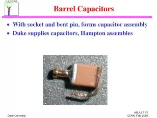
Capacitor installation (~1-2 days/module) Insert capacitors Check capacitor connectivity Check HV traces HV test: caps + wires Seal capacitors Pre-insertion prep. (6 modules/day/2 person) Check ground wire Check cooling sleeve Check mounting holes Active gas fittings, custom made for each module: connection & leak test Glue purging gas gasket Tape HV kapton for protection Glue thermal sensors as needed (4 modules each type) Module preparation
Procedures & tests Fold HV kapton and cover with protection plates Insert module & fix one corner Set module z position to middle of BSS Fix module 2nd corner & attach set screws Check purging gas flow Type 1 1.5 L/min < 10% loss Type 1+2 1.5 L/min < 15% loss Type 1+2+3 0.5 L/min < 20% loss Unfold HV kapton & check traces Attach & glue active gas fittings Plug & seal unused active gas inlets. Leak test active gas volume (1mB/B/min) Install protection boards HV test Check active gas path for obstruction (flow rate test) Module installation
Components modification Peek tubes for module cooling reduced from 0.123”-0.127” 0.116”-0.120” (done) De-magnetization of active gas inlet plugs (started on type 2 modules) Fuse box brackets dimension change Fuse box screws changing from Nylon to Ultem Module repair: Wire removal (2 bad wires + some retroactive decisions from acceptance group) HV trace repair (1) Cooling sleeve replacement (3) Re-glue detached shell & divider (1) Tension plate socket replacement (2) Non-routine module work
Beyond modules • Data Base: Access data base in use for progress tracking. • MTF: Migration in progress. Preliminary tree structure available for review. • Upgrade for space frame bracing (needed for type 3 installation): In progress, some components ready to be installed. • Outer cylinder is yet to be copper shielded. • Gas/Cooling manifold: Expect to have drawings reviewed and submitted for fabrication this month.
Protection boards - 21 type 1 modules installed. 6000 more boards coming. FE assembly – P1.29 installed. 17+ more being prepared DCS : HV, LV, thermal sensors, cooling interlock (CIL) … operational. Electronics installation
Summary • More than half of the modules have been installed! • Procedures are understood and becoming routine. • Module installation expect to finish by the end of the year • Electronics installation has begun.