Download
1 / 26
260 likes | 361 Views
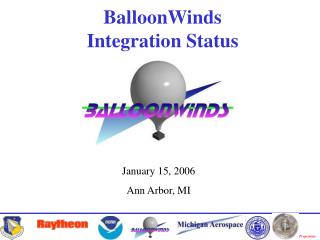
BalloonWinds Update --Straight to Launch--. James M. Ryan University of New Hampshire. BalloonWinds Instrument Overview. Size : 8’x8’x12’ Gondola Mass : 6000 lbs Power Requirements : 1300 W Power System : 26 Lithium-Ion Batteries Thermal Management : Ice and Electric Heaters

E N D
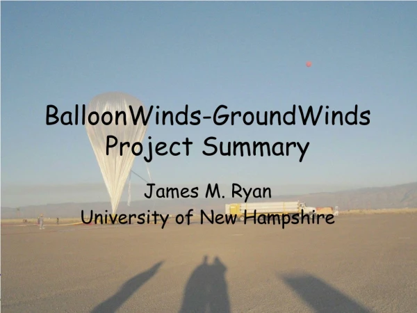
BalloonWinds Update--Straight to Launch-- James M. Ryan University of New Hampshire
BalloonWindsInstrument Overview • Size: 8’x8’x12’ • Gondola Mass: 6000 lbs • Power Requirements: 1300 W • Power System: • 26 Lithium-Ion Batteries • Thermal Management: • Ice and Electric Heaters • Optical Systems: • Diode-Pumped Nd:YAG • ½-meter Telescope • Direct-Detection Receivers (2)
Chamber Reviews Laser Chamber Material 6061-T6 Aluminum Volume (empty) 10 cubic feet Design Pressure 18 psig Test Pressure (Hydrostatic) 28 psig Assembly Test Pressure (Pneumatic) 22.5 psig (1.5 MEOP) Interferometer Chamber Material 304L Stainless Steel Volume 14 cubic feet Design Pressure 16.5 psig Assembly Test Pressure (Pneumatic) 22.5 psig (1.5 MEOP)
Chamber Reviews (cont.) Coolant Tank Material 304L Stainless Steel Volume (empty) 18 cubic feet Design Pressure 18.75 psig Test Pressure (Hydrostatic) 28 psig Assembly Test Pressure (Pneumatic) 22.5 psig (1.5 MEOP) Electronics Chamber Material 304L Stainless Steel Volume (empty) 30 cubic feet Design Pressure 18.75 psig Test Pressure (Hydrostatic) 28 psig Assembly Test Pressure (Pneumatic) 22.5 psig (1.5 MEOP)
Schedule Delay • AFRL postponed environmental tests • Schedule slip by the preceding instrument • Fixed schedule for the succeeding instrument • Test window closed • 6-month slip in launch schedule with rescheduled test date TBD
Rescheduling Process • 2-week window emerged in July-August • New TVAC Facility cleanliness requirements • Assessment began • Flowdown from new requirements • Risk & risk reduction • Impact of risk-mitigation • Environmental test objectives
TVAC Facility • Large investment in facility for two optical payloads • Class-100 inside TVAC chamber • Class-100 outside TVAC chamber • Select material list • No particulates • No liquids or volatiles • No silicone-based materials
Flowdown from New Requirements • Meticulous cleaning of gondola • Prepare comprehensive material list • Removal or encapsulation of forbidden materials • Vacuum grease • Coolant • Insulation • Wood
Risk & Risk Reduction • Facility contamination was primary risk • Risk reduction measures included • Bagging gondola • Reduced altitude simulation • Reduced temperature range (tropopause) • All support equipment located outside facility • No schedule or admittance guarantee after completion of all known requirements
Impact of Risk-Mitigation • Gondola’s thermal properties different from flight configuration • T-P profile not representative of flight profile • Consumable state and burn rate not representative of flight • Limited to one cycle. 2nd cycle logistically impractical.
Environmental Test Objectives • Verification of thermal system operation • Heating/cooling capacities (duty cycles) • System performance (temperatures vs set points) • Time required to equilibrate at final altitude • Revelation of impacts on opto-mechanical and detector systems • Laser: Power, seeding, frequency tuning… • Telescope: Motor control of focus adjustment… • Interferometer: Alignment, stability, motor control… • Detectors: Chip temperature, Gain, read noise…
Environmental Test Objectives (cont.) • Estimation of Mission Duration • Battery power burn rate & “knee” shape • Coolant system capacity & “knee” shape • Pressure chamber leak rates All impacted by risk mitigation efforts Test no longer matched with objectives
Straight to Launch • The new facility requirements • Increased resource requirements • Increased associated risk • Decreased benefit of test • Hindered original test objectives • Environmental tests were cancelled • Environmental test objectives rolled into flight objectives
Added Flight Objectives Procedures & Impacts • Verification of thermal system operation • Monitor temperatures and heating/cooling duty cycles • Modify temperature set points to counteract temperature and/or duty cycle issues • Raw data will be unusable until thermal stead-state is attained and the interferometer is aligned
Added Flight Objectives Procedures & Impacts • Revelation of impacts on opto-mechanical and detector systems • Monitor laser power, spectral widths, optical transmissions, photometric return, etc • Remote adjustments performed to reduce the impact • Raw data black-outs will occur during such adjustments
Added Flight Objectives Procedures & Impacts • Estimation of Mission Duration • Capacity for an 8-hour mission will be assumed • Monitor battery bus voltage, coolant temperature and chamber pressures • Cut-down will be initiated if the following value estimates are reached • Bus voltage limit- 25V • Output manifold temperature- 4C • Chamber pressure limit- 0.8 atm
Advantages of Not Testing • Schedule contingency • Released resources • Reduced risk of mishandling
Laser ChamberPre-Failure Cross-supports 2947½-inch lid (0.35-inch eff. thickness)
Laser ChamberPost-Failure I Cross-supports Secondary fractures from gondola impact Lid bottom Thermal insulation (yellow)
Laser ChamberPost-Failure II Cross-support Secondary fractures from pipe interference Lid bottom Fibertek Laser
Laser ChamberPost-Failure III Reverse angle showing the disorder
Laser ChamberPost-Failure IV Fragments at the bottom of the thermal-vacuum chamber