Download

1 / 12
120 likes | 206 Views
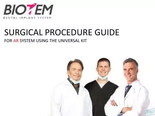
SURGICAL PROCEDURE GUIDE FOR PX SYSTEM USING THE UNIVERSAL KIT. SURGICAL KIT – UNIVERSAL. 2. 1 – Guide Drill 2 – Pilot Drills 3 – Twist Drills 4 – Cortical Drills 5 – Drill Extension 6 – Fixture Driver (Manual) 7 – Fixture Driver (Machine) 8 – Torque Wrench 9 – 1.2mm Hex Driver

E N D
SURGICAL PROCEDURE GUIDEFOR PX SYSTEM USING THE UNIVERSAL KIT
SURGICAL KIT – UNIVERSAL 2 1 – Guide Drill 2 – Pilot Drills 3 – Twist Drills 4 – Cortical Drills 5 – Drill Extension 6 – Fixture Driver (Manual) 7 – Fixture Driver (Machine) 8 – Torque Wrench 9 – 1.2mm Hex Driver 10 – Parallel Pin 11 – 1.2mm Hex Screw 1 3 11 4 5 10 6 7 9 8
GUIDE DRILL Round Drill vs. Point Drill • Round Drill • Risk of slipping may lead to: • Less precise positioning • Damaging bone tissue • BIOTEM Guide Drill • No slipping • Precise Positioning Recommended rotational speed1200 rpm
PILOT DRILLS Marker signals depth reached Groove disperses cooling liquid Recommended rotational speed 700-800 rpm
TWIST DRILLS Marker signals depth reached Groove disperses cooling liquid Recommended rotational speed 700-800 rpm
CORTICAL DRILLS Groove Line sets the limit of drilling Recommended rotational speed 700-800 rpm
DRILL EXTENSION Common connective groove designs create a risk for bending Robust connective capsule design with easy assembly / disassembly
PARALLEL PIN Insert this side into Ø2.0mm osteotomy (after using the straight drill) Insert this side into the implant screw hole
HAND DRIVERS Hex Driver (for torque wrench) Hex Driver (Manual)
FIXTURE DRIVERS For Machine Insertion (contra-angle) Contra-Angle Torque Wrench
Joining the driver with the implant – Simple and Safe 1. Insert driver into the appropriate connective space while applying pressure to the top of the implant holder. 2. Apply pressure at the bottom of the holder in order to release the implant-driver assembly.
DRILLING SEQUENCEPX FIXTURE DRILLING SEQUENCE Ø 3.3mm Ø 4.1mm Ø 4.8mm *soft bone **hard bone 1 2 3 * ** 3 1 2 3