Download
1 / 23
290 likes | 351 Views
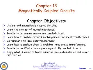
Magnetically Coupled Circuits. Chapter Objectives: Understand magnetically coupled circuits. Learn the concept of mutual inductance. Be able to determine energy in a coupled circuit. Learn how to analyze circuits involving linear and ideal transformers.

E N D
Magnetically Coupled Circuits • Chapter Objectives: • Understand magnetically coupled circuits. • Learn the concept of mutual inductance. • Be able to determine energy in a coupled circuit. • Learn how to analyze circuits involving linear and ideal transformers. • Be familiar with ideal autotransformers. • Learn how to analyze circuits involving three-phase transformers. • Be able to use PSpice to analyze magnetically coupled circuits. • Apply what is learnt to transformer as an isolation device and power distribution Huseyin Bilgekul Eeng224 Circuit Theory II Department of Electrical and Electronic Engineering Eastern Mediterranean University
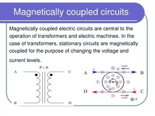
Mutual Inductance • Transformersare constructed of two coils placed so that the charging flux developed by one will link the other. • The coil to which the source is applied is called the primary coil. • The coil to which the load is applied is called the secondary coil. • Three basic operations of a transformer are: • Step up/down • Impedance matching • Isolation
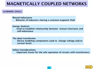
Mutual Inductance • When two coils are placed close to each other, a changing flux in one coil will cause an induced voltage in the second coil. The coils are said to have mutual inductance M, which can either add or subtract from the total inductance depending on if the fields are aiding or opposing. • Mutual inductanceis the ability of one inductor to induce a voltage across a neighboring inductor.
Mutual Inductance b) Mutual inductance M21 of coil 2 with respect to coil 1. a) Magnetic flux produced by a single coil. c) Mutual inductance of M12 of coil 1 with respect to coil 2.
Mutual Inductance • Mutual inductances M12 and M21 are equal. • They are referred as M. • We refer to M as the mutual inductance between two coils. • M is measured in Henry’s. • Mutual inductance exists when two coils are close to each other. • Mutual inductance effect exist when circuits are driven by time varying sources. • Recall that inductors act like short circuits to DC.
Dot Convention If the current ENTERS the dotted terminal of one coil, the reference polarity of the mutual voltage in the second coil is POSITIVE at the dotted terminal of the second coil. If the current LEAVES the dotted terminal of one coil, the reference polarity of the mutual voltage in the second coil is NEGATIVE at the dotted terminal of the second coil.
Coils in Series • The total inductance of two coupled coils in series depend on the placement of the dotted ends of the coils. The mutual inductances may add or subtract. • Series-aiding connection. • L=L1+L2+2M b) Series-opposing connection. L=L1+L2-2M
Time-domain and Frequency-domain Analysis jM V1 I1 jL1 jL2 I2 V2 b) Frequency-domain circuit a) Time-domain circuit
P.P.13.2 Determine the phasor currents j3I2 j3I1 j3I1 + + + - - -
Mutually Induced Voltages I1 I3 I2 + + + + + + + -j50 j20Ic j10Ib j60 j40 j30Ib j20Ia 500 V j30Ic j80 Ib j10Ia 100 Ic Io Ia • To find I0 in the following circuit, we need to write the mesh equations. Let us represent the mutually induced voltages by inserting voltage sources in order to avoid mistakes and confusion. Ia = I1 – I3 Ib = I2 – I1 Ic = I3 – I2 Io = I3 Blue Voltage due to Ia Red Voltage due to Ic Green Voltage due to Ib
Mutually Induced Voltages • To find I0 in the following circuit, we need to write the mesh equations. Let us represent the mutually induced voltages by inserting voltage sources in order to avoid mistakes and confusion.
Energy in a Coupled Circuit • The total energy w stored in a mutually coupled inductor is: • Positive sign is selected if both currents ENTER or LEAVE the dotted terminals. • Otherwise we use Negative sign.
Coupling Coefficient • The Coupling Coefficient kis a measure of the magnetic coupling between two coils • Loosely coupled coil b) Tightly coupled coil
Linear Transformers • A transformer is generally a four-terminal device comprising two or more magnetically coupled coils. • The transformer is called LINEAR if the coils are wound on magnetically linear material. • For a LINEAR TRANSFORMER flux is proportional to current in the windings. • Resistances R1 and R2 account for losses in the coils. • The coils are named as PRIMARY and SECONDARY.
Reflected Impedance for Linear Transformers • Let us obtain the input impedance as seen from the source, ZR • Secondary impedance seen from the primary side is the Reflected Impedance.
Equivalent T Circuit for Linear Transformers • The coupled transformer can equivalently be represented by an EQUIVALENT T circuit using UNCOUPLED INDUCTORS. • Transformer circuit b) Equivalent T circuit of the transformer
Equivalent П Circuit for Linear Transformers • The coupled transformer can equivalently be represented by an EQUIVALENT П circuit using uncoupled inductors. • Transformer circuit b) Equivalent Π circuit of the transformer