Download

1 / 28
290 likes | 330 Views
MAGNETICALLY COUPLED CIRCUIT. OBJECTIVES. To understand the basic concept of self inductance and mutual inductance. To understand the concept of coupling coefficient and dot determination in circuit analysis. SUB - TOPICS. 7-1 SELF AND MUTUAL INDUCTANCE. 7-2 COUPLING COEFFICIENT (K)

E N D
OBJECTIVES • To understand the basic concept of self inductance and mutual inductance. • To understand the concept of coupling coefficient and dot determination in circuit analysis.
SUB - TOPICS 7-1 SELF AND MUTUAL INDUCTANCE. 7-2 COUPLING COEFFICIENT (K) 7-3 DOT DETERMINATION
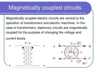
7-1 SELF AND MUTUAL INDUCTANCE • When two loops with or without contacts between them affect each other through the magnetic field generated by one of them, it called magnetically coupled. • Example: transformer • An electrical device designed on the basis of the concept of magnetic coupling. • Used magnetically coupled coils to transfer energy from one circuit to another.
+ V _ Φ i(t) a) Self Inductance • It called self inductance because it relates the voltage induced in a coil by a time varying current in the same coil. • Consider a single inductor with N number of turns when current, i flows through the coil, a magnetic flux, Φ is produces around it. Fig. 1
According to Faraday’s Law, the voltage, v induced in the coil is proportional to N number of turns and rate of change of the magnetic flux, Φ; • But a change in the flux Φ is caused by a change in current, i. Hence; • Thus, (2) into (1) yields; • From equation (3) and (4) the self inductance L is define as; or The unit is in Henrys (H)
b) Mutual Inductance • When two inductors or coils are in close proximity to each other, magnetic flux caused by current in one coil links with the other coil, therefore producing the induced voltage. • Mutual inductance is the ability of one inductor to induce a voltage across a neighboring inductor.
Φ12 + V1 _ + V2 _ L1 L2 i1(t) Φ11 N2 turns N1 turns Consider the following two cases: • Case 1: two coil with self – inductance L1 and L2 which are in close proximity which each other (Fig. 2). Coil 1 has N1 turns, while coil 2 has N2 turns. • Magnetic flux Φ1 from coil 1 has two components; * Φ11 links only coil 1. * Φ12 links both coils. Hence; Φ1 = Φ11 + Φ12 ……. (6) Fig. 2
Thus, voltage induces in coil 1: Voltage induces in coil 2 Subscript 21 in M21 means the mutual inductance on coil 2 due to coil 1
Φ21 + V1 _ + V2 _ L2 L1 i2(t) Φ22 N2 turns N1 turns • Case 2: Same circuit but let current i2 flow in coil 2.(Fig. 3) • The magnetic flux Φ2 from coil 2 has two components: * Φ22 links only coil 2. * Φ21 links both coils. Hence; Φ2 = Φ21 + Φ22 ……. (9) Fig. 3
Thus; voltage induced in coil 2 Subscript 12 in M12 means the Mutual Inductance on coil 1 due to coil 2 Voltage induced in coil 1 Since the two circuits and two current are the same: Mutual inductance M is measured in Henrys (H)
7-2 COUPLING COEFFICIENT, (k) • It is measure of the magnetic coupling between two coils. • Range of k : 0 ≤ k ≤ 1 • k = 0 means the two coils are NOT COUPLED. • k = 1 means the two coils are PERFECTLY COUPLED. • k < 0.5 means the two coils are LOOSELY COUPLED. • k > 0.5 means the two coils are TIGHTLY COUPLED. • k depends on the closeness of two coils, their core, their orientation and their winding. • The coefficient of coupling, k is given by; or
7-3 DOT DETERMINATION • Required to determine polarity of “mutual” induced voltage. • A dot is placed in the circuit at one end of each of the two magnetically coupled coils to indicate the direction of the magnetic flux if current enters that dotted terminal of the coil. Fig. 4
Dot convention is stated as follows: if a current ENTERS the dotted terminal of one coil, the reference polarity of the mutual voltage in the second coil is POSITIVE at the dotted terminal of the second coil. • Alternatively; if a current LEAVES the dotted terminal of one coil, the reference polarity of the mutual voltage in the second coil is NEGATIVE at the dotted terminal of the second coil. • The following dot rule may be used: • when the assumed currents both entered or both leaves a pair of couple coils by the dotted terminals, the signs on the L – terms. • if one current enters by a dotted terminals while the other leaves by a dotted terminal, the sign on the M – terms will be opposite to the signs on the L – terms. • Once the polarity of the mutual voltage is already known, the circuit can be analyzed using mesh method.
Application of the dot convention is illustrated in the four pairs of mutual coupled coils. (Fig. a,b,c,d) The sign of the mutual voltage v2 is determined by the reference polarity for v2 and the direction of i1. Since i1 enters the dotted terminal of coil 1 and v2 is positive at the dotted terminal of coil 2, the mutual voltage is +M di1/dt. (Fig. a) Current i1 enters the dotted terminal of coil 1 and v2 is negative at the dotted terminal of coil 2. The mutual voltage is –M di1/dt. (Fig. b)
Same reasoning with Fig. a and fig. b are applies to the coil in Fig. c and Fig. d.
M M i i i i (+) L1 L2 (-) L1 L2 Dot convention for coils in series Series – aiding connection Series – opposing connection
M R1 ja jb Vs R3 I1 R2 I2 + Below are examples of the sets of equations derived from basic configurations involving mutual inductance • Circuit 1 Solution:
ja R2 R1 M Vs I1 -jc jb I2 + • Circuit 2 Solution:
R1 jb R2 M Vs ja I1 I2 + • Circuit 3 Solution:
-jc ja R1 I2 Vs R2 jb I1 M + • Circuit 4 Solution:
M3 R1 ja jb jc M2 M1 Vs -jd I1 + I2 R2 Circuit 5 Solution:
-j3Ω 4Ω j8Ω j2Ω 100V 5Ω j6Ω + I1 I2 Example 1 Calculate the mesh currents in the circuit shown below. Solution:
In matrix form; The determinants are: Hence:
5Ω j3Ω + Vo _ j2Ω 10V j6Ω -j4Ω + I1 I2 Example 2 Determine the voltage Vo in the circuit shown below. Solution:
In matrix form: Answers:
j3Ω -j4Ω I1 I2 12Ω j5Ω j6Ω + 1 Example 3 Calculate the phasor currents I1 and I2 in the circuit below. Solution: For coil 1, KVL gives; -12 + (-j4+j5)I1 – j3I2 = 0 Or jI1 – j3I2 = 12
3 2 For coil 2, KVL gives; -j3I1 + (12 + j6)I2 = 0 Or I1 = (12 + j6)I2 = (2 – j4)I2 j3 Substituting into : 2 1 (j2 + 4 – j3)I2 = (4 – j)I2 = 12 Or From eqn. and : 2 3