Download

1 / 24
320 likes | 722 Views
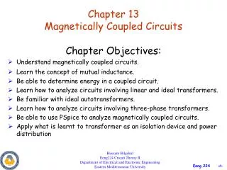
Magnetically Coupled Networks. Magnetically Coupled Networks. A new four-terminal element, the transformer , is introduced in this chapter A transformer is composed of two closely spaced inductors, that is, two or more magnetically coupled coils primary side is connected to the source

E N D
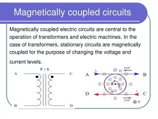
Magnetically Coupled Networks A new four-terminal element, the transformer, is introduced in this chapter A transformer is composed of two closely spaced inductors, that is, two or more magnetically coupled coils primary side is connected to the source secondary side is connected to the load
Dot Convention dot convention: dots are placed beside each coil (inductor) so that if the currents are entering (or leaving) both dotted terminals, then the fluxes add right hand rule says that curling the fingers (of the right hand) around the coil in the direction of the current gives the direction of the magnetic flux based on the direction of the thumb We need dots on the schematic to know how the coils are physically oriented out one another
Mutually Coupled Coils The following equations define the coupling between the two inductors assuming that each respective current enters the dot side which is also the positive voltage sidewhere L1 and L2 are the self-inductances of the coils (inductors), and M is the mutual inductance between the two coils M i1(t) i2(t) + + v1(t) L1 L2 v2(t) – –
EXAMPLE Write a set of mesh-current equations that describe the circuit shown in terms of the currents i1, i2, and i3
(In the following set of mesh-current equations, voltage drops appear as positive quantities on the right-hand side of each equation.) Summing the voltages around the first mesh yields The second mesh equation is The third mesh equation is
Mutually Coupled Coils (AC) The frequency domain model of the coupled circuit is essentially identical to that of the time domain
Source Input ImpedanceLinear Transformer The source sees an input impedance, Zi, that is the sum of the primary impedance, and a reflected impedance, ZR, due to the secondary (load) side M Z + – VS L1 L2 ZL
THE LINEAR TRANSFORMER Transformer source load R1 R2 a c jωM ZS I2 I1 ZL jωL2 jωL1 Vs d source b Load
EXAMPLE The parameters of a certain linear transformer are R1 = 200 Ω, R2 = 100 Ω, L1 = 9 H, L2 = 4 H, and k = 0.5. The transformer couples an impedance consisting of an 800 Ω resistor in series with a 1 µF capacitor to a sinusoidal voltage source. The 300 V (rms) source has an internal impedance of 500 + j100 Ω and a frequency of 400 rad/s. a) Construct a frequency-domain equivalent circuit of the system. b) Calculate the self-impedance of the primary circuit. c) Calculate the self-impedance of the secondary circuit. d) Calculate the impedance reflected into the primary winding. e) Calculate the scaling factor for the reflected impedance. f) Calculate the impedance seen looking into the primary terminals of the transformer. g) Calculate the rms value of the primary and secondary current. h) Calculate the rms value of the voltage at the terminals of the load and source. i) Calculate the average power delivered to the 800 Ω resistor. j) What percentage of the average power delivered to the transformer is delivered to the load?
S 0 L U T I 0 N a) frequency-domain equivalent circuit of the system
c). The self-impedance of the secondary circuit. d). The impedance reflected into the primary winding. e). The scaling factor by which Z22* is reflected is 8/9
f). The impedance seen looking into the primary terminals of the transformer is the impedance of primary winding plus the reflected impedance, thus g). Calculate I1 and I2
j). The average power delivered to the transformer is Therefore
Energy Analysis An energy analysis of the mutually coupled inductors provides an expression for the instantaneous stored energy The sign is positive (+) if currents are both entering (or leaving) the dots; sign is negative (-) if currents are otherwise
Quantifying the Coupling The mutual inductance, M, is in the range The coefficient of coupling (k) between two inductors is defined as for k > 0.5, inductors are said to be tightly coupled for k 0.5, coils are considered to be loosely coupled
DRILL EXERCISE The self-inductances of the coils shown are L1 = 5 mH and L2 = 33.8 mH. If the coefficient of coupling is 0.96, calculate the energy stored in the system in millijoules when (a) i1 = 10 A, i2 = 5 A; (b) i1 = -10 A, i2 = -5 A; (c) i1 = -10 A, i2 = 5 A; and (d) i1 = 10 A, i2 = -5 A.