Download
1 / 48
480 likes | 593 Views
Learn about electron microscopes, types, components, theory of operation, sample preparation, and see images. Includes SEM and TEM details, specimen interaction, and history. Helpful tips on preparing non-conductive samples and biological specimen steps.

E N D
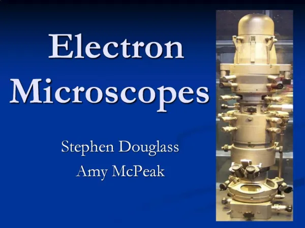
Electron Microscopes Scanning electron microscopes (SEM) Transmission electron microscopes (TEM) System components Theory of operation Sample Preparation Vendors FNI 2C EM
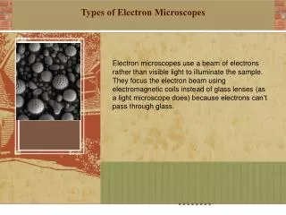
History of the electron microscope Types of electron microscopes SEM TEM Cryo Atmospheric Electron Microscope Images System components Theory of operation Electron beam specimen interaction Detectors Specimen preparation The electron gun The five axis stage The Electron Microscope FNI 2C EM
Introductory SEM Text http://www.jeolusa.com/SERVICESUPPORT/ApplicationsResources/ElectronOptics/DocumentsDownloads/tabid/320/DMXModule/692/Command/Core_ViewDetails/Default.aspx?EntryId=257 FNI 2C EM
Ernst Ruska • Invented the electron microscope in 1931. • The electron microscope obtains images by scanning the surface of a sample with a beam of electrons. http://nobelprize.org/physics/laureates/1986/ruska-autobio.html FNI 2C EM
Older SEM control panel FNI 2C EM
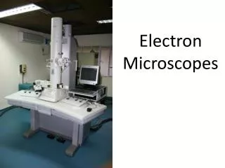
Modern SEM in operation FNI 2C EM
My Ant Rosie with a Micromachined Part FNI 2C EM
Computer Chip Cross Section FNI 2C EM
Leaf FNI 2C EM
Red Blood Cells FNI 2C EM
CVTC SEM FNI 2C EM
Scanning Electron Microscope Components Console Column Display Chamber Control Panel FNI 2C EM
SEM Theory of Operation • An SEM is usually operated under high vacuum of 10-4 Pa or 10-6 Torr. • There is a large voltage difference between the anode and the electron gun cathode typically 10 kV to 40 kV. • When current begins to flow through the filament then electrons begin to be emitted from the filament through field emission. • The electrons are accelerated down the column by the electric potential. • Electrons pass through a series of apertures and magnetic lenses. • The final magnetic lens brings the electron beam into focus on the surface of the sample. FNI 2C EM
Scanning Electron Microscope Components Electron Gun Condenser Lens Electron Beam Scan Coils Final Aperture Final Lens/ Focus Sample Secondary Electron Detector FNI 2C EM
SEM Theory of Operation • The scan coils raster the beam back and forth over the surface of the sample. • Secondary electrons are drawn into the secondary electron detector and amplified. • The signal is translated into bright and dark areas on the monitor. • Magnification is determined by the amount of area scanned. • Magnification can range from 10x to 500,000x • Resolution is approximately 1 nm. FNI 2C EM
Electron Beam Specimen Interactions ~3 nm FNI 2C EM
Inside an SEM chamber Final lens Secondary electron detector Backscattered electron detector FNI 2C EM
Inside CVTC’s SEM chamber Final lens Secondary electron detector Backscattered electron detector FNI 2C EM
Sample Preparation FNI 2C EM
Specimen Preparation Specimen Solid Non-solid Surface preparation Dryable Non-dryable Biological specimen preparation Low moisture High moisture Non-conductive Conductive Metal coating High vacuum High accelerating voltage High Vacuum Low accelerating voltage Low vacuum High vacuum Cryo-technique FNI 2C EM
Sample Preparation • Samples will usually need to be prepared in some way for viewing in an SEM. • Often a coating of gold, palladium or carbon is applied to the sample if the sample is not conductive. • Sometimes a cross sectional sample is required. • To prepare a cross section sample it is first mounted in epoxy. • After the epoxy has hardened the sample is polished on a polishing wheel with different grades of sand paper and grit. • Finally a slurry of sub micron particles can be used to prepare the surface of the sample. • The sample may then be treated with different chemicals to highlight different features of the sample. • These “stains” include HF and Wright etch for semiconductors. • 4% nitric acid in methanol for stainless steel • After the sample is stained then they will be coated with a conductive layer. FNI 2C EM
Colloidal Graphite or Silver Carbon tape Specimen Stub Sample mounting Sample FNI 2C EM
Compression mount sample in plastic block Mounted sample preparation Sand sample on successively finer sand papers. Rotate 90° between grits and inspect under a microscope to ensure previous scratches are polished out. Polish with successively finer polishing slurry. (5 micron to .1 micron) until no scratches are visible under a microscope. Sample may need to be stained or etched with acid after this. FNI 2C EM
Sputter coating Electrically insulating samples must be sputter coated with a layer of metal usually Palladium or Gold. This reactor uses argon excited into a plasma. The argon ions smash into the metal target knocking atoms off like billiard balls. The atoms deposit onto the sample to form a continuous layer. This allows electrons from the electron beam to flow to ground. FNI 2C EM
Biological Sample Preparation Obtain the sample. This may involving toming or obtaining thins sections with a razor blade Fix the sample with gluteraldehyde This is causes cross linking among proteins similar to embalming Displace the water with successively more concentrated ethanol. This may take several hours. Displace the ethanol with liquid CO2 and dry in the critical point dryer to avoid drying with a meniscus. FNI 2C EM
Critical Point Dryer – Caution this operates under high pressure! FNI 2C EM
Electron Gun FNI 2C EM
Thermionic Emission • In thermionic emission a cathode is heated to a high temperature, typically over 1000 K, by flowing electrical current through the filament. This reduces the work function for removing an electron. • There are two main types of thermionic cathodes. • Tungsten (W) • Lanthanum hexaboride (LaB6) FNI 2C EM
Tungsten Cathode • Tungsten Cathode – A filament of tungsten wire is bent into a point. Current is passed through the wire causing it to heat to 2800 K. • The work function for removing an electron from a tungsten cathode is Ew = 4.5 eV. • Tungsten cathodes are inexpensive but they tend to burn out eventually like a light bulb as tungsten atoms evaporates from the surface of the filament. • Temperature: 2800 K. • Work function: Ew = 4.5 eV. • Current density: 5 x 10⁴ A/cm2 • Electron source size: 20 μm • Lifetime: 50-100 hours • Vacuum: 10-4 Pa FNI 2C EM
LaB6 Cathode • Temperature: 1800 K. • Work function: Ew = 2.4 eV. • Current density: 2-3 x 10⁵ A/cm2 • Electron source size: 10 μm • Lifetime: 300-500 hours • Vacuum: 10-2 Pa FNI 2C EM
Cold Cathode Field Emission Gun • A very sharp tip (<100 nm) • The electric field at the tip is > 107 V/cm. • The potential barrier becomes very narrow as well as reduced in height. • Electron tunnel through the barrier and leave the cathode. • Brightness: 107 A/cm2 • Temperature: Room temperature • Brightness: 2-3 x 10⁵ A/cm2 • Electron source size: 5-10 nm • Lifetime: One year or more • Vacuum: 10-8 Pa • High resolution • Can image nonconductive materials at low accelerating voltage (1500 eV) FNI 2C EM
Electron Acceleration Example Consider an electron emitted from a 30 kV electron gun. Calculate how fast it is going (compared to light speed). Calculate its ultimate resolution. Assume a tungsten cathode KE = Eγ-w h = 6.626 x 10⁻³⁴ m2kg/s KE = ½ mv2 c = 2.998x10⁸ m/s 1 eV = 1.602 x 10⁻¹⁹ J me = 9.11x10⁻³¹ kg FNI 2C EM
Sample Stage • The sample is typically placed on a five axis stage in the vacuum chamber. The five dimensions in which the sample can be moved are: • X • Y • Z • Rotation • Tilt FNI 2C EM
A Five Axis Stage Z X Y Tilt Rotation FNI 2C EM
Venting the chamber FNI 2C EM
Imaging FNI 2C EM
Brightness and Contrast FNI 2C EM
Brightness and Contrast FNI 2C EM
Spot size 70 FNI 2C EM
Spot size 18 FNI 2C EM
Spot size 35 FNI 2C EM
Stigmatism FNI 2C EM
Stigmatism Stig X Stig Y FNI 2C EM
Secondary vs. Backscattered FNI 2C EM
Backscattered Electron Images Scan mode 2 (too fast) FNI 2C EM
Backscattered Electron Images Topographical Mode Compositional Mode FNI 2C EM
Burr FNI 2C EM