Download

1 / 22
230 likes | 381 Views
Sequential System Synthesis -- Introduction. Outline. Combinational Circuits vs. Sequential Circuits Flip-Flop Binary cell that can store one bit of information. Basic Flip-Flop Circuit Common Types of Flip-Flops: RS, JK, D, T. Mealy Machine and Moore Machine

E N D
Outline • Combinational Circuits vs. Sequential Circuits • Flip-Flop • Binary cell that can store one bit of information. • Basic Flip-Flop Circuit • Common Types of Flip-Flops: RS, JK, D, T. • Mealy Machine and Moore Machine • Design Flow of Sequential System • Synthesis and Optimization • Examples ENEE 644
Combinational Circuits • A circuit is combinational if it computes a function which depends only on the current inputs applied to the circuit; for every input set of values, there is a unique output set of values. • Acyclic circuits are necessarily combinational • Cyclic circuits can be combinational • in fact, there are combinational circuits whose minimal implementation must have cycles [Kautz 1970] ENEE 644
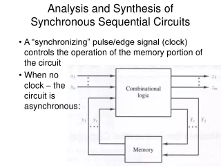
Sequential Circuits • In a sequential circuit, the output values may be different for the same set of input values; the output depends on the current contents of memory elements as well. • Feedback (cyclic) is a necessary condition for a circuit to be sequential. • Synthesis of sequential circuits is not as well developed as combinational. (only small circuits) • Sequential synthesis techniques are not really used in commercial software (except maybe retiming). ENEE 644
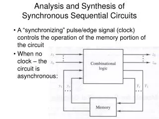
Logic Circuits • Combinational • Sequential x0 z0 Combinational Logic Circuit x1 z1 xn zm outputs inputs Combinational Logic Circuit Memory Elements Sequential Logic Circuit ENEE 644
NAND Gate Flip-Flops Q R 1 2 Q’ S S Q 1 Q’ R 2 Basic Flip-Flop • Two Output (Q and Q’) • Various Ways to Feed Flip-Flops • NOR Gate Flip-Flops ENEE 644
3 1 2 4 RS Flip-Flop S • Three Inputs: • Clock Pulse: additional input to control when state is changing. • S(et) input • R(eset) input • Four States: • Set state: S=1, R=0, CP=1 (Q=1, Q’=0) • Reset state: S=0, R=1, CP=1 (Q=0, Q’=1) • Indetermined: S=1, R=1, CP=1 (Q=1, Q’=1) • No change: S=0, R=0, CP=1 Q S Q > CP Q’ R Q’ R ENEE 644
RS Flip-Flop (cont’d) • Characteristic Equation: Q(t+1) = F(Q(t), S(t+1), R(t+1)) = S + R’Q SR = 0 • Characteristic Table: ENEE 644
K 3 Q 1 CP Q’ 2 J 4 JK Flip-Flop • Three Inputs: • CP: Clock Pulse • J: Set input • K:Reset input J Q > Q’ K • Four States: • Set state: J=1, K=0, CP=1 • Reset state: J=0, K=1, CP=1 • No change: J=0, K=0, CP=1 • Complement: J=1, K=1, CP=1 ENEE 644
JK Flip-Flop (cont’d) • Characteristic Equation: Q(t+1) = F(Q(t), J(t+1), K(t+1)) = JQ’ + K’Q • Characteristic Table: ENEE 644
3 1 2 4 D Flip-Flop D • Two Inputs: • CP: Clock Pulse • D: Set input D’: Reset input Q CP D Q > Q’ Q’ • Two States: • Set state: D=1, CP=1 • Reset state: D=0, CP=1 • Characteristic Equation: Q(t+1) = F(Q(t), D(t+1)) = D ENEE 644
T Flip-Flop • One input JK flip-flop • Two States: • No Change: T=0, CP=1 • Complement: T=1, CP=1 • Characteristic Equation: • Q(t+1) = F(Q(t), T(t+1)) = TQ’+T’Q T 3 Q 1 T Q > CP Q’ Q’ 2 4 ENEE 644
Excitation Table • Excitation table: the reverse of characteristic table, indicates how we should change flip-flop inputs to make the required state transition. excitation table characteristic table ENEE 644
Flip-Flop Excitation Tables ENEE 644
State, State Reduction and Assignment • A state of a sequential circuit is defined by the binary information stored in the memory elements (e.g. flip-flop). • One flip-flop stores one bit, so m flip-flops can define at most 2m states. • Two states are equivalent if for any input, they produce the same outputs and move to the same or equivalent states. • State Reduction problem: reduce the number of flip-flops in a sequential circuit. • State Assignment problem: assign binary values to states such that the cost of the flip-flop input functions is reduced. ENEE 644
Mealy and Moore Models • A sequential system is of Mealy type if output values depend on both present states and inputs. • Recall that a state is a combination of the memory element’s content. • A sequential system is of Moore type if output values depend only on the present states. • This does not mean that output is independent of the inputs. Instead, the impact is through memory units. ENEE 644
Sequential Circuit Design • Given: system description • Goal: logic diagram, Boolean function expression • System specification • State table/transition graph construction • State reduction/minimization • State assignment/encoding • Flip-flop selection • Excitation/output table derivation • Logic simplification/minimization • Logic diagram drawing ENEE 644
next state current state x=0 x=1 0/000 0/001 0/011 1/001 1/011 S3 S2 S1 1/111 1/000 S5 S6 S4 1/110 1/100 0/100 0/110 0/111 Example: Sequential System Design System spec. → state transition table/graph • Design a circuit with one input x and three outputs A,B,C. An external source feeds x one bit per clock cycle, when x=0, the outputs remain no change; otherwise, they repeat the binary sequence: 0,1,3,7,6,4, one at a time. ENEE 644
1/1 1/1 00 10 00 0/1 = 10 01 0/0 0/0 1/0 1/1 0/1 1/0 1/0 01 01 11 11 1/1 0/1 0/0 0/0 Example: Sequential System Design State Minimization/Reduction • Recall that two states are equivalent if for any input, they produce the same outputs and move to the same or equivalent states. We need only one state for all its equivalent states. Therefore, redundant states can be removed and hardware (e.g. flip-flops) can be saved. ENEE 644
0/000 0/001 0/011 1/001 1/011 S3 S2 S1 1/111 1/000 S5 S6 S4 1/110 1/100 0/100 0/110 0/111 Example: Sequential System Design State Assignment/Encoding • The goal is to assign binary values, each bit will be implemented by one flip-flop, to states. • Sequential binary assignment: • S1=001, S2=010, S3=011 S4=100, S5=101, S6=110 • Average bits to be changed: [(0+2)+(0+1)+(0+3)+(0+1)+ (0+2)+(0+3)]/12 = 1 • Ad hoc binary assignment: • S1=000, S2=001, S3=011 S4=111, S5=110, S6=100 • Average bits to be changed: [(0+1)+(0+1)+(0+1)+(0+1)+(0+1)+(0+1)]/12 = 0.5 ENEE 644
1/1 0/1 10 00 0/1 0/0 1/1 1/0 11 01 1/0 0/0 Example: Sequential System Design • System spec. → state transition table/graph → state minimization/encoding → flip-flop selection → excitation/output table derivation Current State Next State Flip-flop inputs ENEE 644
1/1 0/1 10 00 0/1 0/0 1/1 1/0 11 01 1/0 0/0 T T Q Q A B > > CP Q’ Q’ y x Example: Sequential System Design • System spec. → state transition table/graph → state minimization/encoding → flip-flop selection → excitation/output table derivation → logic simplification/minimization → logic diagram drawing • Flip-flop input functions: • TA = A B • TB = (Ax)’ • Output: • y = ABx ENEE 644