Download
1 / 5
60 likes | 327 Views
The disappearing filament principle used in Optical Pyrometers. PLEASE VIEW IN SLIDE SHOW MODE. Navigation-Links Home Optical Pyrometers Radiation Thermometers The E-missivity Trail. Note: Click to advance each slide. Artwork courtesy of Spectrodyne, Inc.

E N D
The disappearing filament principle used in Optical Pyrometers PLEASE VIEW IN SLIDE SHOW MODE. • Navigation-Links • Home • Optical Pyrometers • Radiation Thermometers • The E-missivity Trail Note: Click to advance each slide. Artwork courtesy of Spectrodyne, Inc. Page URL: http://www.temperatures.com/Howopticals.html temperatures.com - 2001
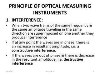
The disappearing filament principle—optical system - Lamp Objective Lens Red Filter Eye lens Field Lens Range Filter Erecting Lens Field Stop Exit Stop Entrance Stop Figure - Optical system of DFP 2000 pyrometer Navigation-Links |Home| |Optical Pyrometers| |Radiation Thermometers| |The E-missivity Trail|
The disappearing filament principle-1. An operator sights onto a hot target, adjusts the range until its image is seen in red. The lamp filament is initially cooler than the target and its image appears as a darker red or black superimposed on the target’s image. Image of Hot Target Image of Filament (Cooler) • Navigation-Links • Home • Optical Pyrometers • Radiation Thermometers • The E-missivity Trail What the operator sees when looking into the eyepiece; the target in red, its surroundings in black (cooler) or red (hot) and superimposed on the target, the filament. The view is circular because the optical system is made up of circular lenses, apertures etc.
The disappearing filament principle-2. The lamp current is raised until the image of the filament becomes hotter than the target and it appears as brighter red than the target. Image of filament (Hotter) • Navigation-Links • Home • Optical Pyrometers • Radiation Thermometers • The E-missivity Trail Pointer indicating the center of the filament. Image of hot target
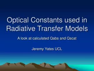
The disappearing filament principle-3. The lamp current is adjusted until the lamp filament’s brightness* temperature equals that of the target. The filament’s image blends into the image of the target. The filament “disappears”. • Navigation-Links • Home • Optical Pyrometers • Radiation Thermometers • The E-missivity Trail * Brightness or radiance temperature is the temperature that a blackbody would have when it looks as bright as the target. It is almost always a lower temperature than the true temperature because of the effect of the target’s emissivity. However if the target is an object in a furnace or oven of about the same temperature, the true and brightness temperatures are very close to the same value. Also, if the target is in a cooler surroundings and has a relatively high emissivity, the difference between the true and brightness temperatures may be small. The difference for a wide range of conditions can be estimated from a table in ASTM Standard E1256.