Download
1 / 58
1.22k likes | 3.36k Views
ECEN 607(ESS ). Low Drop-Out Voltage Regulators. Analog and Mixed-Signal Center, Texas A&M University. Voltage. Battery (i.e. Li-ion). Regulated Voltage. Time. Power Management. Why do we need power management? Batteries discharge “almost” linearly with time.

E N D
ECEN 607(ESS) Low Drop-Out Voltage Regulators Analog and Mixed-Signal Center, Texas A&M University
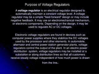
Voltage Battery (i.e. Li-ion) Regulated Voltage Time Power Management • Why do we need power management? • Batteries discharge “almost” linearly with time. • Circuits with reduced power supply that are time dependent operate poorly. Optimal circuit performance can not be obtained. • Mobile applications impose saving power as much as possible. Thus, the sleep-mode and full-power mode must be carefully controlled. • What is the objective of a power converter? • To provide a regulated output voltage
+ + + VREGULATED Battery Battery Battery - - - VREGULATED VREGULATED CP SR LDO LDO CP LDO What are the conventional power converters? • Low drop-out linear regulator (LDO) • Switch-inductor regulator (switching regulators) • Switch-capacitor regulator (charge pump) Why do we need different Power Converters Types? • Different applications • Desired efficiency and output ripple Can we combine them? What is the purpose of combining several converters?
+ RC RLOAD VO VBAT - RC + VC Feedback Control RLOAD VO VBAT - Linear Regulator: Principles • Vo must be constant and • VBAT is changing as a function of time Thus in order to keep constant Vo, the value of the controlling resistor RC yields: How can we automatically pick the value of RC such that Vo= Vdesired, reg-voltage?
a b a b a b VGS VC = VGS VC = -VGS = VSG RC1 RC2 RC1 RC2 a b a b MN MP VC VC How can we implement RC and the Feedback Control? ID Can we implement RC as follows? For which applications? NMOS Transistor PMOS Transistor ILOAD Vdo = ILOADRC VDO,p= VSD(SAT) VDO,n= VSAT+Vgs MN and MP are transistors operating in the Ohmic region. Discuss the option.
VO VO R1 Error Amplifier Error Amplifier R1 VC,NMOS VC,PMOS R2 R2 VREF VREF How the feedback control could be implemented? • Remarks • Make sure the closed loop is negative • For an ideal op amp gain, the differential input is zero, i.e. • VREF is a Bandgap voltage which is also supplied by VBAT=VIN. OR
The efficiency is defined as: • Where VDO is the voltage drop across the pass transistor, i.e. VDS • The output error voltage (EVO) is defined as: OR
VIN Error Amplifier VX gm( Vx – ViN ) Ref rop PMOS Pass Transistor AEA( VDIV - VREF) AEA VIN R1 R1 Io VDIV VDIV RL Load (RL) R2 R2 LDO Analysis • Let us analyze the basic LDO architecture. First, we will consider ideal components, then the non-idealities are introduced together with the accompanied design challenges to tackle VIN = VBAT Vo Basic LDO Topology Small Signal Representation (1) (2)
Solving the (1) and (2), Vo becomes: Where: Thus Vo can be expressed as: If Vo yields: T is the open loop gain. Furthermore for T >>1 Observe that Vin is attenuated by AEAand Vref is not.
Line Regulation The line regulation is a steady-state specification.It can be defined as: For a practical case with non-idealities such as offset Op-Amp voltage and reference voltage error i.e. ; the line regulator becomes: Observe that designers should also minimize: and provide Vref to be independent of VBAT and temperature and process variations.
Note that Rc given in page 3 for a transistor can be expressed as: In order to maintain the regulation the transistor must operate properly NMOS case Exercise: Repeat the above case for a PMOS case
R1 GEA ∆VDIV RL RL Vin Vo+∆Vo R2 VREF Load/Line Regulation Let us assume the error amplifier is a transconductance amplifier of value GEAand α is the current gain of the pass transistor i.e. Thus Io Furthermore: Then, the load regulation can be expressed as: Or line regulation:
Io,max Io,max Io,min Io,min t0 t1 t0 t1 t3 t4 Efficiency Calculation Example of efficiency: A 3.3V LDO with 3.7 V < Vin < 4.71V, 100mA < Io < 150mA Io,q(maximum quiescent current) = 100 μA The output current can be represented as a pulse for simulation purposes OR
Vo Im RESR Re -wL CL LDO ESR Stability One of the most challenging problems in designing LDO is the stability problems due to the closed loop and the parasitic components associated with the pass transistor and the error amplifier. In fact to compensate the loop stability a large external capacitor is often connected at the output. i.e. Where CLis of the order of μF with a small equivalent series resistor (RESR).
LDO Parameters 1 • Dropout voltage (Vdo); This is the difference between the minimum voltage the input DC supply can attain and the regulated output voltage. • Input rail range; This is the input supply voltage range that can be regulated. The lower limit is dependent on the dropout voltage and upper limit on the process capability. • Output current range; This is the output current handling capability of the regulated output voltage. The minimum current limit is mainly dependent on the stability requirements and the maximum limit dependent on Safe Operating Area (SOA) of pass FET and also maintaining output voltage in regulation. • Output capacitor range; This is the specified output capacitance the regulator is expected to accommodate without going unstable for a given load current range. • Output regulated voltage range; This is the output voltage variation the regulator guarantees. When output voltage is in this range, it is said to be in regulation. • Load regulation; This is the variation in output voltage as current moves from min to max
LDO Parameters 2 • Line regulation; This the variation in output voltage as supply • voltage is varied from minimum to maximum. • PSR; Power Supply Rejection ( or ripple rejection) is a measure of the • ac coupling between the input supply voltage on the output voltage. • Load/Line transient regulation; This is a measure of the response speed • of the regulator when subjected to a fast load/Vsupply change. • Short circuit current limit; This is the current drawn when the • output voltage is short circuited to ground. The lower limit is • determined by the maximum regulated load current and the upper • limit is mainly determined by the SOA and specified requirements • Power Efficiency; This is the ratio of the output load power • consumption to input supply power. Linear regulators are not really • efficient especially at high input supply voltages. • Overshoot: It is important to minimized high transient voltages at start-up and during load and line transients. • Thermal Shut down: This is needed to protect the part from damage
VIN Error Amplifier CGs PND1 VREF PD C Rds Vout PND2 B CGD R1 CL RL A D z 1EH 1EF R2 RESR VTest Loop Breaking Point for Stability Analysis Conventional LDO: Modeling Close Loop Schematic Open Loop Transfer Function: RPAR : Output impedance RL : Load resistance RDS : Drain to source impedance of the pass transistor R1 &R2 : Feedback Resistors Open Loop Block Diagram Vdropout : Minimum voltage drop across the input and output terminalsof the LDO with shich the system is able to regulate. VDSSATPass : Vdsat of the pass transistor Note: The error amplifier is a two-stage amplifier without miller compensation
Dominant pole Cgate Error Amplifier AEA • CGATE is connected to output node. • Miller Compensation is not required since the dominant pole is at the output. Two stage amplifier without miller compensation Notes:
Pass Transistor Transconductance Dominant Pole / Compensation Zero Non-dominat Pole due to Pass Transistor Gate Capacitance Error Amplifier Nondominant Pole Feedback Factor Matlab/Simulink Macromodel Formulas and Component Values
Loop Gain ~ 100dB Fu ~ 2.7MHz Phase boost due to Compensation Zero PM ~ 90° Simulation Results From Simulink Loop Gain and Phase
Open Loop Gain and Phase Under Load Variation Notes: 1-Open Loop System 2- Load Variation (iload varies from 10mA to 50mA) 3- The load variation (iload) was simulated in Matlab using a “for loop”
Simulation Results From Matlab Step Response Vout varies from 0 to 3.3V Vin varies from 0 to 3.5V
Vsupply Power Supply Rejection • Problem: • Low frequency and high frequency noise affects the operation of the highly sensitive circuits • External noise is mainly coupled through the supply lines • A regulator (LDO) is mandatory with high PSR
VIN VDD VIN VIN VIN Power Supply Rejection Existing Solutions • Current Solutions: • RC filtering: Larger drop-out voltage, and larger power consumption • Cascading of LDO: Larger area, power consumption, larger drop-out voltage • Combined RC filtering and cascading: Larger area and power consumption, larger drop-out voltage and complexity
Enhancing PSR over a wide frequency range Proposed Topology • The NMOS cascode, MNC, shields the entire regulator from fluctuations in the power supply. • MNC gate needs to be biased at a voltage above the supply using a charge pump. • MNC acts as a voltage follower for noise at its gate, it is critical to shield the gate of MNC from supply fluctuations using an RC filter to shunt supply ripple to ground. G. A. Rincon-Mora, V. Gupta, “A 5mA 0.6mA CMOS Miller-Compensated LDO Regulator with -27dB Worst-Case Power-Supply Rejection Using 60pF of On-Chip Capacitance ,” ISSCC, feb. 2007.
Enhancing PSR over a wide frequency range • With the help of an NMOS cascode, a charge pump, a voltage reference and an RC filter to shield the entire regulator from power supply fluctuations, a 5mA LDO regulator utilizing 60pF of on-chip capacitance achieves a worst-case PSR performance of -27dB over 50MHz. G. A. Rincon-Mora, V. Gupta, “A 5mA 0.6mA CMOS Miller-Compensated LDO Regulator with -27dB Worst-Case Power-Supply Rejection Using 60pF of On-Chip Capacitance ,” ISSCC, feb. 2007.
Stability and PSR Simulations • Stability test (Open Loop) Frequency Response Open loop gain shows a low pass frequency response AC signal is injected here Loop Gain ~ 65dB Fu ~ 10MHz PM ~ 60°
Stability and PSR Simulations (Continue) • PSR simulation AC signal is injected here PSR versus Frequency PSR curve shows a Quasi-Band Pass frequency response it is less than -40 dB up to 10KHz, -30 dB at 100 KHz
Different Compensation Techniques for Stability Purposes • Internal zero generation using a differentiator • An auxiliary fast loop (differentiator) provides both a fast transient detector path as well as internal ac compensation. • The simplest coupling network might be a unity gain current buffer. • Cf senses the changes in the output voltage in the form of a current that is then injected into pass transistor gate capacitance. Robert J. Milliken, Jose Silva-Martínez, and Edgar Sánchez-Sinencio “Full on-chip CMOS low-dropout voltage regulator,” IEEE Trans. on Circuits and Systems – I, pp 1879-1890, vol. 54, Issue 9, Sept. 2007.
Different Compensation Techniques • Capacitive feedback for frequency compensation • It introduces a left hand plane zero in the feedback loop to replace the zero generated by ESR of the output capacitor. • the capacitor is split into two frequency-dependent voltage-controlled current sources (VCCS) and grounded capacitors. • Instead of adding a pole–zero pair with zero at lower frequency than the pole, in this technique only a zero is added. • It needs a frequency dependent voltage control current source (VCCS). Chaitanya K. Chava, and Jose Silva-Martinez, “A frequency compensation scheme for LDO voltage regulators,” IEEE Trans. on Circuits and Systems – I, vol. 51, No.6, pp. 1041-1050, June 2004.
Different Compensation Techniques • DFC frequency compensation • It is a pole-splitting compensation technique especially designed for compensating amplifier with large-capacitive load. • DFC block composed of a negative gain stage with a compensation capacitor Cm2, and it is connected at output of the first stage. Another compensation capacitor Cm1 is required to achieve pole-splitting effect. • The feedback-resistive network creates a medium frequency zero for improving the LDO stability. K. N. Leung, and P.K.T. Mok, “A capacitor-free CMOS low-dropout regulator with damping-factor-control frequency compensation,” IEEE J. Solid-State Circuits, vol.38, no.10, pp.1691-1702, Oct. 2003.
Different Compensation Techniques • Pole-zero tracking frequency compensation • To have pole-zero cancellation, the position of the output pole po and compensation zero zc should match each other. • The resistor is implemented using a transistor Mc in the linear region, where its value is controlled by the gate terminal. K. C. Kwok, P. K. T. Mok. “Pole-zero tracking frequency compensation for low dropout regulator,” 2002 IEEE International Symposium on Circuits and Systems, Vol. IV, pp. 735-738,May 2002.
Fast Transient Response • A current-efficient adaptively biased regulation scheme is implemented using a low-voltage high-speed super current mirror. It does not require a compensation capacitor. • The adaptively error amplifier drives a small transconductance (MA9) to modulate the output current IOUT through a transient-enhanced super current mirror. Yat Lei Lam, Wing-Hung Ki, “A 0.9V 0.35µm Adaptively Biased CMOS LDO Regulator with Fast Transient Response,” 2008 IEEE International Solid-State Circuit Conference, February 2008.
Noise in Linear Regulators • LDO noise is sometimes confused with PSRR • PSRR is the amount of ripple on the output coming from the ripple of the input. • On the other hand, noise is purely a physical phenomenon that occurs with the transistors and resistors (ideally, capacitors are noise free) on a very fundamental level. • Primary noise sources: 1. Bandgap-Reference (Primary source of noise) • Possible solution: add a low-pass filter (LPF) to the output of the bandgap. • Drawback: it can slow down the output startup. 2. The resistor divider ( thermal noise = 4KTR ) • Possible solution: Use resistors as small as possible. • Drawback: Smaller resistors burn more current through the feedback divider. • Possible solution: add a capacitor across the top resistor in the resistor feedback divider. At high frequencies it reduces the close loop gain and thus the noise. • Drawback: it could slow down start-up time significantly, since the capacitor would have to be charged by the current in the resistor divider. 3. Input stage of the error amplifier (thermal and flicker noise) • Possible Solution: Large input drivers. • Drawback: larger area. • Second order noise sources: • Load current and output capacitance (Phase Margin) • Low phase margin will cause peaking in the close-loop gain and since the close-loop gain amplifies this noise, the total output noise increases. Reference: J. C. Teel, “Understanding noise in linear regulators” Analog Application Journal, 2Q 2005, www.ti.com/aaj
Conventional LDO Error Amplifier Pass Transistor VREF R1 CL RL VOUT R2 RESR LDO Design Example
Design Flow Diagram Vin Vout ILoad RL Vdropout W/L Design Error Amplifier Cp Rp RA CGate RDS Calculate non dominant poles: PND1, PND2 Adjust poles and zeros locations using CL and RESR Check stability Check transient, PSR, load regulation, line regulation, …
LDO Design Example Since Assuming µPCox= 65µA/V2 the pass transistor size can be calculated by: In order to minimize the gate capacitance, we use minimum length L = 0.6µm The gate capacitance of the pass transistor is given by the following equation: where
Design Example (Continue) The values of CGS and CGD can be also obtained if we run a dc simulation and verify the operating point of the pass transistor. Using the last method, we found: R1 and R2 are calculated using : Assuming a reference voltage of 1.2V and choosing R1 = 240K, We found R2 = 420K .
Design Example (Continue) Error Amplifier Design and Considerations • High DC Gain to guarantee high loop gain over the range of loads (AV > 60dB) • Low output impedance for higher frequency pole created with CGS of pass transistor • Internal poles must be kept at high frequencies, preferably > fU of the system (~1MHz) • Low DC current consumption • Low Noise Error Amplifier schematic The error amplifier is implemented using a two stage without miller compensation topology in order to achieve a gain larger than 60dB and GBW =7MHz using 0.5µm CMOS technology
Design Example (Continue) Error Amplifier Simulation Results Phase Plot Magnitude Plot Note: This results were obtained using Cgate = 36.5pF as the load
Design Example (Continue) Pole / Zero Locations Dominant Pole Location Second non-dominant pole location Zero location First non-dominant pole location Notes: 1- RA was obtained from simulations. Basically, it is the output resistance of the error amplifier. 2-PND2 is greater than 7.3MHz since the phase margin of the amplifier is around 51°. This is good news since we want this pole to be located above the gain bandwidth product of the overall system. 3- RESR equal 5 was chosen for stability reasons (see next slide).
Design Example (Continue) Stability versus RESR UGB versus RESR Phase margin versus RESR Note: RESR was swept from 0 to 10
Design Example (Continue) System Simulation Results Magnitude Plot (IL=50mA) Phase Plot (IL=50mA) Phase Margin = 55° DC Gain = 74dB UGB = 6.3MHz Phase Plot (IL=100µA) Magnitude Plot (IL=100µA) Phase Margin = 90° DC Gain = 75dB UGB = 172KHz
Design Example (Continue) System Simulation Results VIN Step Plot IL Step Plot Load Regulation = Line Regulation = Notes: 1- VIN step from 3.4 to 3.5V 2- ILOAD step from 0 to 50mA
PSR versus Frequency Design Example (Continue) System Simulation Results PSR @ 100KHz = -35dB
Current Efficient LDO For low IL, for R1+R2 >> Ro_pass Note that RL is significantly larger Loop Gain: For no-load current
Note that GB will change as changes, this effects modify the pole-zero locations and the phase margin. i.e., Current Efficient LDO Due to current mirror when load current exist, then we have make The zero is located at: Another pole is located at the output of the AEA, G. A. Rincon-Mora, P. E. Allen, “A low-voltage, low quiescent current, low drop-out regulator,” IEEE J. Solid-State Circuits, vol.33, no.1, pp.36-44, Jan. 1998.
Aopen Avo p1 p2 p3 z To determine the stability one can consider the open loop gain defined as: where Stability imposes the following conditions: where Where o is defined as: Or Phase Margin:
For ; is the arbitrary phase margin In order to determine an approximated relation between p3 and GB several assumptions are required. Avo >> 1, Then tan-1(Avo) 90° Thus one can write