Download
1 / 27
270 likes | 358 Views
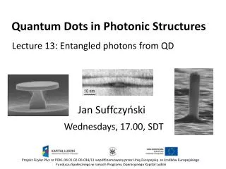
Applicazioni Fotonica 4: Photonic enhancement in emission. QDs light emitters: what next?. Increase the repetition rate Increse the emission efficiency Electrical injection GaAs QDs on Si subtrates. Photonics. Relazione NF e FF Diffrazione Kirchhoff. Different Diffraction Geometry.

E N D
Applicazioni Fotonica 4: Photonic enhancement in emission
QDs light emitters: what next? • Increase the repetition rate • Increse the emission efficiency • Electrical injection • GaAs QDs on Si subtrates Photonics
Relazione NF e FF Diffrazione Kirchhoff
Different Diffraction Geometry We wish to find the light electric field at large distance r after diffraction Observation sphere Near filed E(x,y) y1 y R P1 x x1 P r E(q,f) This region is assumed to be much smaller than this one. Incident wave What is E(q,f) at a distance r from the center of the plane of NF
Diffraction Solution on a generic FF surface The field in the observation surface (x1,y1,z1), is given by where:
Fresnel limit We have to approximate the phase where is a constant for a spherical surface The important point is that |x-x1|/z1, |y-y1|/z1are always smaller than 1. .
Fraunhofer limit We have to approximate the phase where is a constant for a spherical surface where are the polar angles The important point is that x1/r, y1/r are always smaller than 1. To be more precise ka2/r<<2p or a2/lr<<1 (a2/lr is the Fresnel number) This formulation holds also for large angles.
Fraunhofer limit Then We can write this result in terms of the off-axis k-vector components: and:
a2/lr1 a2/lr>>1 a2/lr<1 r Far field=FT(NF) Fresnel diffraction Near field
Aumento del rate radiativo In cavità Effetto Purcell Nel vuoto Fattore di Purcell Confronto
Q factor in planar cavities R R dI dI dI dI Per massimizzare il Q factor si deve ridurre le perdite della cavità
Predicting the FF from the NF Near field is localized within the photonic defect and it has a spatial modulation equal to the lattice constant
d 2r0 a 2r Cosa stiamo facendo al LENS: Simultaneous engineering of Q & the angular pattern
d 2r0 a 2r High extraction & directionality FF Best Q Engineering of Q r=109 nm d=28 nm
d 2r0 a 2r High extraction & directionality FF Q=25000 h0.5=3 h0.3=1.6 Q=20000 h0.5=12 h0.3=6.5 Q=15000 h0.5=20 h0.3=10 Simultaneous engineering of Q & the angular pattern r=109 nm d=28 nm r=101 nm d=28 nm r=101 nm d=34 nm
Vantaggi MC Microcavità 1. Controllo direzionalità di emissione, aumento efficienza di estrazione 2. Effetto Purcell, aumento rate di emissione


![Crafting Rich Experiences with Progressive Enhancement [Beyond Tellerrand 2011]](https://cdn4.slideserve.com/7565246/crafting-rich-experiences-with-progressive-dt.jpg)
![There Are No “Buts” in Progressive Enhancement [Øredev 2015]](https://cdn4.slideserve.com/7568391/slide1-dt.jpg)