Download
1 / 36
390 likes | 616 Views
GEO600. Harald Lück. Ruthe, 4.9.2003. Worldwide Interferometer Network. 10 kW at Beam Splitter. ~ 5 kW. 5 W. 10 W. 1 W. Light power (specs). Optical Layout. Michelson Interferometer. Mode Cleaners. Laser. 600m. Output Mode Cleaner. ~50mW. GEO 600 Sensitivity (specs.).

E N D
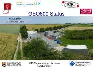
GEO600 Harald Lück Ruthe, 4.9.2003
10 kW at Beam Splitter ~ 5 kW 5 W 10 W 1 W Light power (specs) Optical Layout Michelson Interferometer Mode Cleaners Laser 600m Output Mode Cleaner ~50mW
Strain sensitivity [1/sqrt(Hz)] Frequency [Hz] Tunable Sensitivity TMSR = 0,1% TMSR = 1% TMSR = 5% Therm. noise
300W at Beam Splitter 1W 10W 2W ~10mW Light Power (current) Michelson Interferometer Mode Cleaners Laser R=98.65% Mode Cleaners: Troughput 80% 72% Finesse 2700 1900 Visibility 96% 92% Power Recycling Cavity: Mode matching 97% Finesse 450 Linewidth 270 Hz Output Mode Cleaner
Optical Layout Main Interferometer Mode Cleaner Laser Bench Output Bench
entrance to vacuumsystem Slave Slave Master Master • Master Laser: • Nd:YAG • NPRO (non-planar ring oscillator) • 800mW @ 1064 nm • Slave Laser: • Nd:YAG • injection-locked ring cavity • 14 W @ 1064nm • less than 5% in higher modes Laser System
STS2 GEO Triple Pendulum Suspension passive active D-space
Thermal Noise Issues Intermediate mass Monolithic Suspension Weld Glas Fibres (coated) Silicate (Hydroxy- Catalysis) Bonding Mirror
Laser Frequency Stabilisation: • no rigid reference cavity • laser is directly stabilised to suspended cavities • 3 sequential Pound- Drever-Hall control loops • common mode of the Power-Recycled Michelson serves as frequency reference Frequency and Length Control Mode Cleaners 25 MHz Michelson Interferometer 13 MHz 37 MHz Laser Output Mode Cleaner
Differential arm length: • (gravitational wave signal) • heterodyne detection • Schnupp modulation • round trip arm difference • ~10cm Michelson Length Control Mode Cleaners Michelson Interferometer 15 MHz Laser 10 MHz • Signal-Recycling control: • separate modulation • frequency • reflected beam from beam splitter AR coating UGF ~400Hz Output Mode Cleaner
<10Hz >10Hz • Electrostatic actuation on test mass bias 500V, range 0-800V= 4µm Test Mass Actuators • Reaction Pendulum: • 3 coil-magnet actuators at intermediate mass • range ~100µm
+2 at MI (differential mode) +2 at Signal-Recycling cavity 16 spot position control Alignment Control Alignment Control 4 degrees of freedom at MC 1 +4 at MC 2 +4 at MI (common mode) Fast AA + 20 = 36 Fast AA Fast AA differential wave-front sensing
Magnet/coil actuators on IM UGF: ~10Hz • Reduces misalignment below 50 nrad rms • Reliable locking over long timescales. Duty cycle >98% Diff. MI Fast Auto-Alignment Output port
System Control • Detector control is done with analog electronics and supervised by a digital LabView system (~200 control loops, ~1000 channels) • Pre-alignment, Auto-alignment, Drift control • Lock acquisition • Operator interactions
GEO sensitivity during S1 run S1: 17days, Aug02-Sep02, longest lock: 121h, duty cycle 98.5%
Final Optics Installation Fall 2002: Exchanged last test optics for final optics
Output mode Radii Of Curvature of folding mirrors do not match East ROC: 687m North ROC: 666m Spec: 640m
10 W 15 W
30 W 15 W
51 W 15 W
60 W 15 W
60 W 15 W
71 W 15 W
74 W 15 W
Final Optics Installation Fall 2002: Implementation of Signal Recycling mirror
Data Acquisition • VxWorks/Tornado based DAQ • 24-bit ADC interface: 32 + (2*) 16 channels up to 16kSample/sec • 12-bit ADC interface: 64 channels with 512 Sample/s • LabView system acquires ~ 1000 channels @ ~1Hz • ca . 60 GB/day
raw data frame data Data Acquisition System GEO site Hannover data collecting units (DCUs) DAQ computer frame maker LabView detector control Radio Link raw data frame data detector status database tape writer Capacity:3 days
Hannover (13 nodes) Golm (180x2 nodes) Glasgow (24 nodes) B‘ham(100x2 nodes) Cardiff (64 nodes) burst analysis, DCR, GEO++ monitorshigh mass inspiral cw analysisburst analysis directed pulsar searchBayesian burst search pulsar normal modes,GW background,inspiral inspiral, periodicand bursts analysis frame data Data Analysis Network Berlin tape archive Cardiff tape archive HDD capacity 100days
Hardware injection of simulated cw signals GPS antenna Control computer sign data acquisition system LAL digitalPLL 4 MHz 1 PPS divider 50 kHz optical isolation 50 kHz Microcontroller 1 PPS GPS time phase accumulator modulo 2 to IFO sine table phase increment register Multiplication amplitude DDS (direct digital synthesiser) phase error of less than 1% (of a full cycle) on timescales of months, recoverable from interruptions
Suspension Dr. Hartmut Grote Control, Aligment Dr. Michael Plissi Uta Weiland Data related issues Stefan Goßler Dr. Morag Casey Labview Control Dr. Kasem Mossavi Vacuum Tour Guides