Download
1 / 28
280 likes | 404 Views
LAT Environmental Test Planning and Design Review 3-4 May 2005 LAT EGSE and Cable Layouts. Rich Bielawski. Outline. LAT EGSE LAT Power and Monitoring LAT Power Rack LAT Control Rack VSC Test Cable Layouts High Bay Ops Vibe Acoustic EMI TVAC. Power and Monitoring EGSE for LAT.

E N D
LAT Environmental Test Planning and Design Review 3-4 May 2005 LAT EGSE and Cable Layouts Rich Bielawski
Outline • LAT EGSE • LAT Power and Monitoring • LAT Power Rack • LAT Control Rack • VSC • Test Cable Layouts • High Bay Ops • Vibe • Acoustic • EMI • TVAC
VSC Cable adapter and signal conditioning MVE 2304 To LAT shield Primary 1553 interface Science interfaces GPS receiver SIU/discrete interface
LAT Environmental Test Planning and Design Review 3-4 May 2005 Cable Layouts Rich Bielawski
Cable Layout - High Bay Operations (1/2) • Configuration • EGSE may be located inside clean tent if there is room otherwise it will be located just outside the clean tent • All are point-to-point cables from LAT connector saver to EGSE • No unregulated power cables • Thermostatically controlled survival heaters will not activate at ambient temperatures • Unique Cable Requirements • Design cables so that same cable set can be used in Dynamics and EMI testing • Interfaces • SC-LAT interface connectors are per the SC-LAT ICD • JL-39 and JL-69 (test ports) are per LAT-DS-02139 • BPU interface is per the SC-LAT ICD • VSC, external test point interface, external crate interfaces are SCSI except for the 1553 interface which is per the SC-LAT ICD
Cable Layout - High Bay Operations (2/2) • Statistics • Cable Count: 26 • Drawings Required: 11 • Taking advantage of similar cable designs • Near-Term Tasks • Create wirelist • Determine cable lengths as these cables will also be used in other test phases • Begin cable drawings • Procure cable parts i.e. wire, connectors, backshells, etc
Cable Layout - Vibration Testing (1/2) • Configuration • LAT EGSE and test cables are located inside vibe room • During the actual vibe test, all LAT EGSE cables are demated except for connector savers and accel cables. • LAT is cabled up for LPT’s, i.e. between vibe axes. • Uses same cables as High Bay Ops. • Unique Cable Requirements • None
Cable Layout - Vibration Testing (2/2) • Interfaces • Accels • NRL accel boom interface is BNC • EMI shield interface defined in LAT-DS-02139 • Accel cable connectors are defined • Adaptors are needed in some cases • LAT EGSE test cables • See High Bay Ops slide • Statistics • Accels cables • Cable count: 37 • Drawings required: 0 (cables are purchased off-the-shelf) • LAT EGSE test cables • See High Bay Ops slide • Near-Term Tasks • Accel cables • Most cables have been procured already • Need to verify quantity • Need to procure interface adaptors • LAT test cables • Same as in High Bay Ops slide
Cable Layout – Acoustic (1/2) • Configuration • LAT EGSE and test cables are located just outside of main chamber door. • During the actual acoustic test, all LAT test cables are demated except for connector savers and accel cables. • LAT is cabled up for LPT’s, i.e. pre- and post-test. • Main chamber door is opened and test cables are routed through doorway to the LAT • Use same cables as High Bay Ops • Unique Cable Requirements • None
Cable Layout – Acoustic (2/2) • Interfaces • Same interfaces as in Vibration Testing slide • Statistics • Accels cables • Cable count: 47 • Drawings required: 0 (cables are purchased off-the-shelf) • LAT test cables • See High Bay Ops slide • Near-Term Tasks • Same as in Vibration Testing slide • Accel cables • Most cables have been procured already • Need to verify quantity • Need to procure interface adaptors • LAT test cables • Same as in High Bay Ops slide
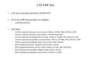
Cable Layout – EMI (Radiated) • Configuration • LAT EGSE located in control room • LAT cables mated during test • Cables fed through opening in chamber wall • Uses same cables as High Bay Ops • Unique Cable Requirements • EMI shielded cables and connector savers are required. • Interfaces • Same interfaces as in High Bay Ops slide • Statistics • Same status as in High Bay Ops slide • Near-Term Tasks • Same status as in High Bay Ops slide
Cable Layout – EMI (Conducted) • Configuration • LAT EGSE located in control room • LAT cables mated during test • Cables fed through opening in chamber wall • Uses same cables as High Bay Ops except for DAQ and SIU power cables • Unique Cable Requirements • EMI shielded cables and connector savers are required • Need to break-out power leads for DAQ and SIU feeds • Interfaces • Same interfaces as in High Bay Ops slide except for the DAQ and SIU power cables • DAQ and SIU power cables have an additional intermediate interface to terminal blocks • Statistics • Cables required: 22 high bay cables + 8 breakout power cables • Cable drawings required: 4 • Only for unique power cables • Taking advantage of similar cables • Near-Term Tasks • Work out details of the terminal block interface • Begin cable drawings • Procure cable and terminal block interface parts
Cable Layout – TVAC (1/3) • Configuration • EGSE is located near port plates used by LAT • Cables are P2P or breakout into two connectors • Includes unregulated feed cables • Unique Cable Requirements • Inside chamber cables and connector savers must be TVAC compatible • Inside chamber cables must be baked out prior to LAT TVAC
Cable Layout – TVAC (2/3) • Interfaces • LAT interface • SC-LAT interface connectors are per the SC-LAT ICD • JL-39, JL-69, JL-264, JL-266 (test ports) are per LAT-DS-02139 • ACD flyaway thermistor connector is TBD • TC terminal block interface is TBD • Chamber interface • Copper paths • Feed thru’s: Glenair 257-135-24-61 (61-pin circular) • Mating connector on cables: Amphenol MS3475L2461S • Thermocouples • Feed thru’s: Deutsch DM5623-37-37PP (37-pin circular) • Mating connector on cables • Deutsch 13084-37S-5020 (inside chamber) • Deutsch DS07-37S-081 (outside chamber) • BPU interface is per the SC-LAT ICD • VSC, external test point interface, external crate interfaces are SCSI except for the 1553 interface which is per the SC-LAT ICD • NRL Thermal Data Acquisition System interface is defined • NRL is responsible for the thermocouple cables
Cable Layout – TVAC (3/3) • Statistics • Cable count: 72 • Drawings required: 36 • Taking advantage of similar cables • Near-Term Tasks • Finalize GSE heater power requirements • Procure long-lead items ASAP, i.e. chamber feed thru’s • Close loop with ACD thermistor interface and terminal block interface • Create wirelist • Determine cable lengths • Begin cable drawings • Procure cable parts i.e. wire, connectors, backshells, etc