Download
1 / 38
380 likes | 479 Views
Agenda: LAT Environmental Test TIM, Day 1: Structural. Introduction 8:30 – 8:45 Morning Planning Meeting 8:45 – 12:00 Sine Vibration Test Planning Meeting 8:45 – 10:15 Acoustic Test Planning Meeting 10:30 – 12:00 Lunch 12:00 – 1:00 Facility Tour 1:00 – 3:15

E N D
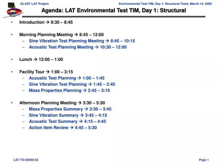
Agenda: LAT Environmental Test TIM, Day 1: Structural • Introduction 8:30 – 8:45 • Morning Planning Meeting 8:45 – 12:00 • Sine Vibration Test Planning Meeting 8:45 – 10:15 • Acoustic Test Planning Meeting 10:30 – 12:00 • Lunch 12:00 – 1:00 • Facility Tour 1:00 – 3:15 • Acoustic Test Planning 1:00 – 1:45 • Sine Vibration Test Planning 1:45 – 2:45 • Mass Properties Planning 2:45 – 3:15 • Afternoon Planning Meeting 3:30 – 5:30 • Mass Properties Summary 3:30 – 3:45 • Sine Vibration Summary 3:45 – 4:15 • Acoustic Test Summary 4:15 – 4:45 • Action Item Review 4:45 – 5:30
Agenda: Morning Planning Meeting • Sine Vibration Test Planning Meeting 8:45 – 12:00 • Action Item List Status (JK) 8:45 – 9:00 • Status of the Test Plan (JK) 9:00 – 9:15 • Detailed Test Sequence and Current Test Configuration (JK) 9:15 – 10:00 • Other Logistics (All) 10:00 – 10:15 • Break 10:15 – 10:30 • Acoustic Test Planning Meeting 10:30 – 12:00 • Action Item List Status (JK) 10:30 – 10:45 • Status of the Test Plan (JK) 10:45 – 11:00 • Detailed Test Sequence and Current Test Configuration (JK) 11:00 – 11:45 • Other Logistics (All) 11:45 – 12:00
Sine Vibration Test Planning: Updated Action Item Status (cont)
Sine Vibration Test Planning: Test Plan Status • Objectives of the test are well understood by all • Verify the strength of the LAT and subsystem interfaces under PFQ loads and durations • Measure primary natural frequencies (fn) of the primary modes of the LAT • Determine transmissibility (Q) of the LAT • Validate the math model used for coupled loads analysis • Verify the workmanship and processes used in the manufacture and assembly • Test Plan • Many technical details have been addressed in previous meeting, and just need to be collected and summarized – many of these points will be raised today, and agreements made will go directly into plan • Instrumentation list is nearing completion, but not finished yet • Internal accelerometers defined and CAD layout complete • External accelerometer mathematical positions defined, but CAD layout needed • Strain gauges (12 channels) on flexures expected, but not defined yet (NRL can accommodate up to 40 channels, ¼ bridge) • Entrance/Exit criteria are well understood by all • No failure or damage to the LAT assembly as determined by physical inspection • No significant changes to the dynamic signature as determined by the pre and post low-level sine vibration inputs • No significant degradation of instrument or system performance
Sine Vibration Test Planning: Test Plan Status (cont.) • Test Personnel • Test support personnel have been identified (to be verified) • Test Director: John Ku (SLAC) • Test Conductor: Bob Haynes (NRL) • Discipline Lead: Jim Haughton (NRL) • Facility Manager:Bill Raynor (NRL) • MGSE Lead: Martin Nordby (SLAC) • EGSE Lead: Mike Huffer (SLAC) • Test Script Lead: Rich Baun (SLAC) • High-bay operations: Paul Dizon (NRL) • Quality Assurance: Darren Marsh (or Doug Bartholomew) (SLAC) • I&T: Ken Fouts (SLAC) • Subcommittees will be assembled from the appropriate personnel above, with expert consultation brought in if needed • Potential Vibration Experts: Paul Baird; Chris Fransen; Bill Haile
Sine Vibration Test Planning: Test Plan Status (cont.) • Test Requirements • Instrument Verification Plan • The tests will be performed to the levels published in the LAT environmental specification document, LAT-SS-00778 • The dynamics tests are to be performed in the mode in which the equipment will observe the environment • LAT will be launched in a “powered off” mode • The sine vibration tests will be performed with the article powered off • EGSE Constraints • Cables • If harnesses are heavy, they should be disconnected during vibration • Must be long enough to reach LAT while mounted to either expander head or slip table • Cable trays or protection if laid on floor • Cart with EGSE Hardware • Portable, can be rolled out of the way • Power interface to lab?
Sine Vibration Test Planning: Test Plan Status (cont.) • Test Requirements • MGSE Constraints • Test Interface Plate • Accommodates Spectrum-specified flexure mounting procedures • Should not have any modes less than 225 Hz (1.5 X 150 Hz) • Should be one order of magnitude stiffer than the flexures • Mass should be small enough to not significantly impact Z-axis test • Light enough to allow for using GPR to lift LAT+TIP within its current rated load (3000 kg) • CG should be in-line with LAT and should position LAT CG through each drive axis • Sufficient strength to carry all test loads with margin • Interface with NRL slip table and expander head • Cable support structures • Should allow free motion of cables between vibration equipment and ground • Should be grounded well to prevent tipping • Allow access to vibe equipment, connector panels, blankets and externally mounted accelerometers • Test stand / handling dolly • Should be grounded well to prevent rolling • Should be located near shaker, and accessible by the vibe lab crane • Radiator mass simulator needed? • Contamination/environmental • MGSE Concept being worked on at SLAC (Martin Nordby)
Sine Vibe: Mechanical Issues • Known issues to be worked
Sine Vibe: Test Configuration Test Interface Plate fits completely on expander head LAT appears toclear rotationof expander head Check on clearance to off-load frame LAT on Expander Head (with auxiliary support) LAT on Shaker Table
Sine Vibe: Test Configuration (cont.) Check on total height of 4x4 Lift Fixture lifting GPR over top of ACD Check on clearance and access around underside of GPR LAT on Expander HeadShowing GPR Lift with 4x4 Lift Fixture
Sine Vibe: MGSE Concept • Test Interface Plate • Provides single interface for LAT in all test configurations • Mimics SC top deck • Ensures accurate alignment of SC flexures Plate serves only to accurately position brackets, not to carry vibe loads Test Interface Plate with SC Flexures(on expander head) Mount brackets transfer load from flexure directly to table Test Interface Plate with SC Flexures(on slip table)
Sine Vibration Test Planning: Detailed Sequence • Pre-test Activities • Move dolly into position in vibration lab and disconnect LAT from dolly (SLAC-IFCT) • Lift LAT and TIP onto expander head, and torque bolts (NRL) • Cable Hook-ups and system checkouts • Electrical connections to shaker system and accel tap checks (NRL) • Electrical connections to EGSE and perform LPT on expander head (SLAC) • Z-Axis Vibration Test • Low-level Signature Sine Sweep to 150 Hz (sweep up and down) • Set-up sheet printouts (NRL), verification and approval (SLAC) • If LPT results are okay, disconnect EGSE cables • Run test • Output FRF data (NRL) • Review Data (SLAC) • Determine notching, if needed • Provide feedback to test conductor • Check pass/fail criteria for Modal Test requirement • Give OK to proceed (SLAC), or decide alternate action is needed • Half-level run to 50 Hz • Set-up sheet printouts (NRL), verification and approval (SLAC) • Run test • Output data hardcopies (NRL) • Review Data (SLAC) • Check notching and adjust, if needed • Provide feedback to test conductor • Give OK to proceed (SLAC), or decide alternate action is needed
Sine Vibration Test Planning: Detailed Sequence (cont.) • Z-Axis Vibration Test (continued) • Full-level run to 50 Hz • Set-up sheet printouts (NRL), verification and approval (SLAC) • Run test • Output data hardcopies (NRL) • Review Data (SLAC) • Check peak levels • Check pass/fail criteria for Modal Test requirement • Give OK to proceed (SLAC), or decide alternate action is needed • Low-level Signature Sine Sweep to 150 Hz • Set-up sheet printouts (NRL), verification and approval (SLAC) • Run test • Output data overlays (NRL) • Review Data (SLAC) • Re-Check pass/fail criteria for Modal Test requirement • Concurrent with data review, hook-up EGSE and perform LPT • If data review and LPT are good, Give OK to break configuration, or decide is alternate action is needed • Post- Z-Test / Pre- X-Test Activities • Disconnect all electrical connections • Remove mounting bolts and move LAT from expander head and set on handling dolly • Remove expander head, rotate shaker to horizontal position and attach drive bar to slip table • Lift LAT and TIP onto slip table for X-axis vibration and torque bolts • Hook-up accelerometers only and perform vibration control system checkout (no EGSE hook-up here)
Y Y X X LAT LAT Sine Vibration Test Planning: Detailed Sequence (cont.) • X-Axis Vibration Test • Low-level Signature Sine Sweep to 150 Hz • Same steps as Z-axis test • Give OK to proceed (SLAC), or decide alternate action is needed • Half-level run to 50 Hz • Same steps as Z-axis test • Give OK to proceed (SLAC), or decide alternate action is needed • Full-level run to 50 Hz • Same steps as Z-axis test • Give OK to proceed (SLAC), or decide alternate action is needed • Low-level Signature Sine Sweep to 150 Hz • Same steps as Z-axis test • Concurrent with data review, hook-up EGSE and perform LPT • If data review and LPT are good, Give OK to break configuration, or decide is alternate action is needed • Post- X-Test / Pre- Y-Test Activities • Disconnect EGSE electrical connections, leaving Accel cables connected • Remove mounting bolts, lift and rotate LAT in place • Lower LAT to slip table and torque bolts • Perform vibration control system checkout (no EGSE hook-up here) Shaker Slip Table Shaker Slip Table
Sine Vibration Test Planning: Detailed Sequence (cont.) • Y-Axis Vibration Test • Low-level Signature Sine Sweep to 150 Hz • Same steps as X-axis test • Give OK to proceed (SLAC), or decide alternate action is needed • Half-level run to 50 Hz • Same steps as X-axis test • Give OK to proceed (SLAC), or decide alternate action is needed • Full-level run to 50 Hz • Same steps as X-axis test • Give OK to proceed (SLAC), or decide alternate action is needed • Low-level Signature Sine Sweep to 150 Hz • Same steps as X-axis test • Concurrent with data review, hook-up EGSE and perform LPT • If data review and LPT are good, Give OK to break configuration, or decide is alternate action is needed • Post- Y-Test Activities • Disconnect all electrical connections • Remove mounting bolts, lift and set LAT on handling dolly • Attach LAT to handling dolly
Sine Vibration Test Planning: Test Configuration • Mechanical Configuration • Radiators not attached • Are mass simulators required to represent load path from radiators? • Currently no mass simulators are baselined • Mounted to GD/Spectrum Astro-provided test flexures • Test flexures will be proof tested at SLAC prior to GRID static test • TIP to interface test flexures and slip table/expander head • LAT Z-axis is always vertical • Access to connectors needed (scaffold around expander head?) on +X side • Layout needed to check cable run lengths • Electrical Configuration • Voltage type accelerometers have BNC connectors to interface with NRL • Strain gauges do not have connectors (open leads) • EGSE needed for LPTs between axes (Rich Baun to define requirements) • Procedures • LAT-MD-00408: LAT Instrument Performance Verification Plan • LAT-MD-02717: LAT Environmental Test Sequence • LAT-MD-01196: LAT Dynamics Test Plan • LAT-MD-01533: LAT EGSE Plan • LAT-MD-00649: LAT Transportation and Handling Plan • LAT-MD-00404: LAT Contamination Control Plan • LAT-SS-00778: LAT Environmental Spec • LAT-TD-00890: LAT Instrumentation Plan
Sine Vibration Test Planning: Logistics and A/I Closure Plans • Many logistics can be discussed during the tour • Any issues rotating shaker • Verify slip table and expander head size, inserts and pattern • CG Alignment / sensitivity of equipment to offsets • Instrumentation patch panels and cable supports • Floor space to set GPR and other GSE down • Capability and benefit of using force gauges • Clearance to off-load frame on expander head • Verify that Test Interface Plate fits completely on expander head • Verify that LAT clears bracket parts on slip table • Complete and release drawings/model of slip table and expander head • Complete detailed design and analysis of TIP and flexure mount brackets • Check on hook height in vibe room to ensure we can remove GPR when LAT is on expander head • Develop paper doll work-up to verify we have floor space for 2 carts, GPR, and 4x4 Lift Fixture • Develop requirements for Radiator simulator for sine vibe • Lay out EGSE cable routing and locate EGSE crates • Identify what contamination and humidity control is needed in vibe facility • Verify response / control channel capability • Is GN2 purge neccesary? • Cleanliness (need blanket?) • Contingencies • Need to be prepared to perform a modal test if the LAT frequencies do not meet expectations • Modal test will not need additional instrumentation • May require the use of portable shaker with stinger to RMB or other hardpoint • Impact to schedule is not believed to be more than one day of testing (but rigorous post test data reduction will be needed) • A/I Closure plans • Any action items unanswered by the end of the meeting will be tracked on a weekly basis • Let’s take a 15 minute break
Acoustic Test Planning: Test Plan Status • Objectives of the test are well understood by all • The objective of the acoustic test is to demonstrate that the fully integrated LAT is capable of withstanding acoustic noise loads, simulating launch conditions. • A secondary objective is to verify the acoustic analysis, i.e. that the LAT components were qualified to high enough levels of Random vibration • Test Plan • Many technical details have been addressed in previous meetings, and just need to be collected and summarized – many of these points will be raised today, and agreements made will go directly into plan • Instrumentation list is nearing completion, but not finished yet • Internal accelerometers defined and CAD layout complete • External accelerometer mathematical positions defined, but CAD layout needed • Strain gauges (12 channels) on flexures expected, but not defined yet • Entrance/Exit criteria are well understood by all • No failure or damage to the LAT assembly as determined by physical inspection • Inspection of plastic sheet under LAT does not produce any fibers, chips or fasteners • No significant changes to the dynamic signature as determined by the pre and post low-level acoustic vibration inputs • No permanent deformations in the LAT structure or of any subsystem or component • No significant degradation of instrument or system performance
Acoustic Test Planning: Test Plan Status (cont.) • Test Personnel • Test support personnel have been identified (to be verified) • Test Director: John Ku (SLAC) • Test Conductor: Bob Haynes (NRL) • Discipline Lead: Jim Haughton (NRL) • Facility Manager:Bill Raynor (NRL) • MGSE Lead: Martin Nordby (SLAC) • EGSE Lead: Mike Huffer (SLAC) • Test Script Lead: Rich Baun (SLAC) • High-bay operations: Paul Dizon (NRL) • Quality Assurance: Darren Marsh (or Doug Bartholomew) (SLAC) • I&T: Ken Fouts (SLAC) • Subcommittees will be assembled from the appropriate personnel above, with expert consultation brought in if needed • Potential Vibration Experts: Paul Baird; Chris Fransen; Bill Haile
Acoustic Test Planning: Test Plan Status (cont.) • Test Requirements • Instrument Verification Plan • The tests will be performed to the levels published in the LAT environmental specification document, LAT-SS-00778 • The dynamics tests are to be performed in the mode in which the equipment will observe the environment • LAT will be launched in a “powered off” mode • The acoustic test will be performed with the article powered off • EGSE Constraints • Cables • Must be long enough to reach LAT while mounted to test stand • Cart with EGSE Hardware • Portable, can be rolled into and out of the chamber, if needed • If cart is moved, does EGSE system need to be checked out again? • Power interface to lab?
Acoustic Test Planning: Test Plan Status (cont.) • Test Requirements • MGSE Constraints • Test Interface Plate • Should be one order of magnitude stiffer than the flexures • Sufficient strength to carry all test loads with margin • Can serve as SC top plate simulator • Cable support structures • Should allow free motion of cables between vibration equipment and ground • Should be grounded well to prevent tipping • Allow access to connector panels, blankets and externally mounted accelerometers • Test stand / handling dolly • Must accommodate mounting of radiators, with lower strut supports simulated • The LAT should be positioned such that the flat panels are a minimum of 15° from parallel to any of the test cell walls (45° preferred) • Current strut design has rattle – design to be flight-like? • Radiator plane should be lined up with high flow (2000 cfm) woofer to prevent air foil effect • Contamination: is tenting needed; humidity • MGSE Concept being worked on at SLAC (Martin Nordby)
Acoustic Test: Test Configuration and MGSE This configuration is identical to EMI Test configuration Test Interface Plate mounts LAT to Test Stand Facsimile SC struts support Radiators with comparable stiffness Need to establish required height off ground—can be handled by a separate stand LAT on Test Stand(one Radiator removed
Acoustic Test Planning: Detailed Sequence • Pre-test Activities • Chamber Setup and empty cell calibration • This is needed to verify the test cell is clean and ready to accept the LAT for testing • The empty cell calibration will verify that the specified sound pressure levels can be achieved • Move LAT on dolly (radiators already installed) into chamber and secure dolly to chamber floor (orientation 45° TBD) • Cable Hook-ups and system checkouts • Electrical connections to shaker system and accel tap checks (NRL) • Electrical connections to EGSE and perform LPT on expander head (SLAC) • LPT on acoustic test stand • Low-Level run at -6 dB for 30 seconds (establish pre-test signature, review data) • Set-up sheet printouts (NRL), verification and approval (SLAC) • If LPT results okay, disconnect EGSE cables and close chamber door • Purge chamber of air • Run Test • Output Data, accel ASD’s and strain gauge SSD’s (NRL) • Review data (SLAC) • Check for “dead” channels • Review mic average for level and chamber uniformity • Review Grms values for obvious anomalies • Give Okay to proceeed (SLAC), or decide if alternate action is needed
Acoustic Test Planning: Detailed Sequence (cont.) • Full-Level run at -0 dB for 60 seconds (impart full SPL, check SPL, linearity, review data) • Set-up sheet printouts (NRL), verification and approval (SLAC) • Run Full level Test • As level steps up to -3dB, check critical channel linearity and record data • Hold at full level for 60 seconds • Immediately following full level run, perform low level run • Do not review data between full level and post-test low level run • Output Data accel ASD’s and strain gauge SSD’s (NRL) • Review data (SLAC) • Check for “dead” channels • Review mic average that PFQ level is met and chamber uniformity • Review Grms values for linearity • Give Okay to proceeed (SLAC), or decide if alternate action is needed
Acoustic Test Planning: Detailed Sequence (cont.) • Low-Level run at -6 dB for 30 seconds (Signature check, review data, complete axis) • Output Data (NRL) • Review data (SLAC) • Check for “dead” channels • Review mic average for level and chamber uniformity • Review pre- and post- test overlays for frequency shifts and amplitude changes • Give Okay to proceeed (SLAC), or decide if alternate action is needed • Post- Acoustic Test Activities • Fill chamber with air (may be done automatically following final low-level run • Connect EGSE and perform LPT • Visually inspect plastic sheet under LAT • If everything looks okay, give okay to break configuration • Disconnect all electrical connections • Disconnect dolly from floor and move LAT out of chamber
Acoustic Test Planning: Test Configuration • Mechanical Configuration • Radiators attached (with flight thermal joint) • Need to ensure thermal joint has enough time to cure (7 days RT) • Mounted to GD/Spectrum Astro-provided test flexures • Test flexures will be proof tested at SLAC prior to GRID static test • Mounted on LAT acoustic test stand • LAT Z-axis is vertical • Access to connectors needed (temporary scaffold or ladder around MGSE) on +X side • Layout needed to check cable run lengths • Electrical Configuration • Voltage type accelerometers have BNC connectors to interface with NRL • Strain gauges do not have connectors (open leads) • EGSE needed for LPTs before and after test (Rich Baun to define requirements) • Procedures • LAT-MD-00408: LAT Instrument Performance Verification Plan • LAT-MD-02717: LAT Environmental Test Sequence • LAT-MD-01196: LAT Dynamics Test Plan • LAT-MD-01533: LAT EGSE Plan • LAT-MD-00649: LAT Transportation and Handling Plan • LAT-MD-00404: LAT Contamination Control Plan • LAT-SS-00778: LAT Environmental Spec • LAT-TD-00890: LAT Instrumentation Plan
Acoustic Test Planning: Logistics and A/I Closure Plans • Many logistics can be discussed during the tour • Lip at threshold (how to transport into room) • Mic placement / adjustability • Cleanliness (need blanket?) – is rating worse than 100K? • Height off ground (Chris Fransen believes current configuration should be okay, but need to check) • Placement in room (note any obstructions) • Note flow rate of pneumatic horns and possible currents in chamber • Instrumentation feedthrough and cable supports • Floor inserts to secure LAT • Is a dust tent needed around LAT in acoustic chamber • What type of panels are needed in/around LAT to simulate SC response • Accommodation for moving Test Stand over ½” door sill • How high does Radiator need to be off the floor: affects Test Stand spacer height • A/I Closure plans • Any action items unanswered by the end of the meeting will be tracked on a weekly basis • Let’s take a lunch break and come back for the tour
Agenda: Facilities Tour • Acoustic Test Planning 1:00 – 1:45 • Overview (BR) 1:00 – 1:10 • Run through test sequence described earlier (JK) 1:10 – 1:25 • Other things to discuss (All) 1:25 – 1:45 • Sine Vibration Test Planning 1:45 – 2:45 • Overview (BR) 1:45 – 1:55 • Run through test sequence described earlier (JK) 1:55 – 2:10 • Things to discuss (All) 2:10 – 2:30 • Control room (BR) 2:30 – 2:45 • Mass Properties Planning 2:45 – 3:15 • Overview (BR) 2:45 – 2:55 • Action Item List Status (JK) 2:55 – 3:00 • Run through test sequence (JK) 3:00 – 3:10 • Discuss capabilities of spin table and decide is MOI is needed (All) 3:10 – 3:15
Facilities Tour: Mass Properties • Mass Properties Planning 2:45 – 3:15 • Overview (BR) 2:45 – 2:55 • Action Item List Status (JK) 2:55 – 3:00 • Run through test sequence (JK) 3:00 – 3:10 • Remove non-flight instrumentation • Move LAT and dolly into mass properties area • Lift LAT onto MOI table and measure mass, Izz, and Xcg and Ycg • Turn Dolly over to Z-horizontal configuration • Attach three load cells beneath handling dolly and measure mass and Z-cg • Turn dolly back to Z-vertical position • Return LAT to Dolly • Turn LAT and dolly over to Z-horizontal configuration • Measure combined mass and Zcg • Discuss capabilities of spin table and MOI (pendulum) table and decide is MOI is needed (All) 3:10 – 3:15 • Configuration • LAT Mass properties may be a combination of measured and calculated properties • Radiators off • On LAT handling dolly for Z-axis measurement
Agenda: Afternoon Planning Meeting • Mass Properties Summary 3:30 – 3:45 • Agreements made today (JK) 3:30 – 3:35 • Items that still need to be worked out (All) 3:35 – 3:40 • Path to test (JK) 3:40 – 3:45 • Sine Vibration Summary 3:45 – 4:15 • Agreements made today (JK) 3:45 – 3:55 • Items that still need to be worked out (All) 3:55 – 4:05 • Path to test (JK) 4:05 – 4:15 • Acoustic Test Summary 4:15 – 4:45 • Agreements made today (JK) 4:15 – 4:25 • Items that still need to be worked out (All) 4:25 – 4:35 • Path to test (JK) 4:35 – 4:45 • Action Item Review 4:45 – 5:30 • Collect action items (JK) 4:45 – 5:00 • Read through action items (JK) 5:00 – 5:15 • Other? (All) 5:15 – 5:30
Mass Properties Summary • Agreements made today • MOI & Spin table is not ideal for our needs • Static CG and Mass measurement can be accomplished with load cells • If we want a 2mm CG resolution, then a 15lbf load cell resolution is needed • Static LAT mass is up to 3000 kg (6614 lbf). • If three load cells are used, each load cell should be rated to 2205 lbf +/- 15lbf • Items that still need to be worked out • Check IRD & MAR for CG requirement • Reqmt is <20mm for Xcg and Ycg • Reqmt is <185mm above LIP • Path to test
Sine Vibration Summary • Agreements made today • EGSE out of room if cables are long enough (desirement, not requirement) • Verification of accels at SLAC using a 1g shaker before mounting, tap check and touch check after mounting • Keep full level vibe spectrum as is (with changes in sweep rate) • Low level sine sweep up and down • NRL to provide accel hookup to LAT • QA managed by SLAC (Darren Marsh), but staffed by SLAC and NRL • Proof Test MGSE at SLAC • Items that still need to be worked out • Structural analysis of TIP and associated MGSE • Is mass simulator for radiators needed • Determine need for force gauges • Simulate LAT on fixture to check for fixture modes • Path to test • Force gauge decision by 3/25 • Release test plan by 3/25 • Plan for Mid to late April PDR (with most A/I’s closed) • Complete pretest analysis and release memo one month prior to test
Acoustic Summary • Agreements made today • No straps needed • Radiators low to floor (3-5cm) is okay • Line up radiator plane to main woofer output • Omit mid-level run just monitor and collect data • Go from full level to low level immediately (no data review) • Use wheels instead of air bearings need to decide on pneumatic or solid tires • Items that still need to be worked out • Verify top plate adequately simulated with MGSE • Path to test • Release test plan by 3/25 • Complete pretest analysis and release memo one month prior to test
Dynamics Tests Action Item Form • Topic / presentation slide number: • Submitted by: • Actionee: • Request: • Reason / Comment: