Download
1 / 33
350 likes | 601 Views
June 14/15, 2007. Radiation Effects on Emerging Electronic Materials and Devices. Radiation Effects in Emerging Materials Overview. Leonard C. Feldman Vanderbilt University Department of Physics and Astronomy Vanderbilt Institute on Nanoscale Science and Engineering. Topics of Interest

E N D
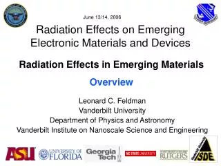
June 14/15, 2007 Radiation Effects on Emerging Electronic Materials and Devices Radiation Effects in Emerging Materials Overview Leonard C. Feldman Vanderbilt University Department of Physics and Astronomy Vanderbilt Institute on Nanoscale Science and Engineering
Topics of Interest Basic radiation interaction with electronic materials-review, educational, modifications at the nanoscale Alternate Dielectrics and Gate Stacks-in all aspects-growth, spectroscopy, radiation effects SiGe devices and other “alternate substrates” (Ge, InGaAs, SiC) Strained silicon
Gate oxide Si metal MOS Schematic Basic radiation interaction with electronic materials- review, educational, modifications at the nanoscale Tutorials and review: Interaction of x-rays with MOS devices occurs primarily via the generation of (photo) electrons in the metal and the underlying silicon. The energetic electrons (<= 10 KeV) create electron hole pairs in the dielectric which may be trapped by “processing” defects. The dielectric is too thin to incur any substantial direct defect production by the primary radiation. The outgoing electrons are too low in energy for direct displacements, but create further secondarys, and possibly defects, through bond breaking leading eventually to e-h pair production.
MAJOR POINT FROM THE PREVIOUIS CONSIDERATIONS “Processing defects”, defects from the imperfection of the grown dielectric, are the primary trapping centers even for the higher atomic number, physically thicker HfO2 “Processing defects”, defects from the imperfection of the grown dielectric, are the primary trapping centers -nanocrystalline HfO2 -HfO2/SiO2 interface -classic defects such as oxygen vacancies, etc -Hf penetration into the SiO2 layer and its interaction with H
interface 2 Å 4 Å 1 nm distance (Å) Number of Hf atoms versus distance from interface Single Hf atoms inside SiO2 interlayer
Gate oxide Si metal MOS Schematic Basic radiation interaction with electronic materials- modifications at the nanoscale Nanoscale: Basic theory of e-h pair production, particularly ε, the average energy required for e-h pair creation, is based on bulk concepts, including bulk density of states. The nanoscale thicknesses, and the new understanding of nanoscale effects calls for re-examination of these concepts. ΔV=Q/C=Ne {(dE/dx) tox/ε} /C ε= average energy/e-h pair Ne= number of electrons penetrating the dielectric
ε= 2.6Eg + K Shockley-Klein εvs. Eg
Rutgers CMOS Materials Analysis Use high resolution characterization methods to: Determine composition, structure and electronic properties gate stacks that use new (post-Si) materials Help determine physical and chemical nature of radiation induced defects Surface/interface analysis: • Ion scattering: RBS, MEIS, NRA, ERD – composition, crystallinity, depth profiles, H/D • Direct, inverse and internal photoemission – electronic structure, band alignment, defects • Scanning probe microscopy – topography, surface damage, electrical defects
Si High-k Metal Defects High-κ Dielectric Metal Electrode DOS Barrier? SiO2 Monolayer? EF Band edge states 10nm Source Drain Ge, III-V CMOS gate ~2010? Materials stability, band alignment and defects in CMOS nanoelectronics L. Goncharova, S. Rangan, O. Celik, C.L. Hsueh, R.A. Bartynski, T. Gustafsson and E. Garfunkel Departments of Chemistry and Physics, and Institute for Advanced Materials, Devices and Nanoelectronics Rutgers University, Piscataway, NJ Collaboration: Vanderbilt, Sematech, NIST, IMEC, IBM, Intel, Bell Labs, NCSU, Penn State, Stanford, UT-Dallas, UT-Austin, Albany.…
Al S2- HfO2 5Å InGaOx InGaAs(001) Defects in the post-Si era:Al/HfO2/InxGa1-xAs • Surface passivation and composition of interfacial layer • High-K deposition • Post-deposition annealing • Metal gate effects • “Normal” and radiation induced defects – nature and evolution
length scales of order and defects in nano-crystalline and non-crystalline Hf-based gate dielectrics Gerry Lucovsky students and post doc: S. Lee, JP Long, H Seo and LB Fleming collaborators: J Whitten, D Aspnes, Jan Luning (SSRL), G. Bersuker and P Lysaght (Sematech) objective: determine the effect of different length scales of order for nano- and non-crystalline Hf based dielectrics on pre-existing intrinsic defects, and then on radiation (X-ray) induced defects approach i) prepare NCSU samples by plasma-CVD ii) determine electronic structure, Hf d-state relative energies, by near edge X-ray absorption, soft X-ray photoelectron spectroscopy, and vis-VUV spectroscopic ellipsometry usingsymmetry adopted linear combinations (SALC-FA Cotton) of atomic states as a guideline iii) study electrical properties in MOSCAPs and compare electrical and X-ray stress
significant results length scale, lcoh - coherent Hf dp – O pp p-bond inter-PUC coupling asymmetric h/e trapping +/- defects X-ray stress phase-sep. silicates and type I lcoh ~ 2 nm or < 5 PUCs no J-T splittings and band-tail defects type II lcoh > 3 nm or > 6 PUCs J-T splittings and discrete band-edge defects J-T splitting 1.2 eV Hf Si oxynitrides- high Si3N4 % no inter-group Hf dp-O pp-bonding no phase-separation, but only for small range of compositions very low tunneling, ~12 (to 16-18) positive charge defects - X-ray stress HfO2 and Hf silicates both positive/negative charged defects
direct bonding HfO2 : Ge(100) electricals being studied and measurements extended to Ge(111) GeO and GeN removed during annealresonant X-rays reveal buried interface substrate specific p-bonds SiON interface/Ge-direct
Gate Source Drain Body p+ n+ n+ p-well p-substrate HfO2 sample details HfO2 based nMOSFET Samples Experimental • State-of-the-art samples, SEMATECH, Inc. • 65 nm technology node • nMOSFETs with W/L = 10m/0.2m • tphys = 7.5 nm and 3.0 nm (EOT = 1.2 nm and 0.5 nm) • SiO2 interlayer (~ 8Å) • 10 keV X-rays, RT irradiation • Function of dose • Function of bias • Characterization done using I-V measurements
HfO2 total dose results • nMOSFETs with W/L = 10m/0.2m tphys = 7.5 nm tphys = 3.0 nm • Thinner dielectric traps significantly less charge S. K. Dixit et al., “ Radiation induced charge trapping in ultra-thin HfO2 based MOSFETs”, accepted for NSREC 2007
HfO2 results HfO2/TiN TiN HfO2 SiO2 p-Si EC Ei n-MOSFET cross-section Ef • Carrier injection from tunneling • Si- surface condition dependent • Both electron and hole trapping observed • Predominant bulk hole trapping (radiation) • Zero bias - radiation induced trapping EV
Hafnium silicates Limitations of HfO2: HfO2 - low thermal budget ~ 500°C Nanocrystalline HfO2 formed during PMA Dopant penetration is an issue Need for HfSiO: • Increased thermal budget to ~ 1000°C • Reduction in dielectric constant Crystallization introduces defects and shallow traps at the grain boundaries Radiation response expected to be better for silicates
E0 = 1.4 MeV 4He E1 = KE0 RBS & CV of HfSiO/SiO2/p-Si films Electrical characterization Physicalcharacterization Total dielectric thickness from RBS: ~10 to 11nm Total dielectric thickness from CV: ~12nm
Results C-V results RBS results • Initial results confirm the trend (… Hf r)
TID Response of Hf0.6 and Hf0.3 Films • Devices prepared by RPECVD; EOT ~ 4 nm • Two dielectric films: • Hf0.6 (containing crystalline HfO2) • Hf0.3 (amorphous) • Electron trapping observed in the Hf0.6 film under large positive bias Probable explanation: e-trapping at nanocrystalline grain boundaries
TID Response Comparison to Previous Hf Silicate Films • TID-induced charge trapping improved compared to previous Hf silicate devices [J. A. Felix et al., IEEE Trans. Nucl. Sci., vol. 49, pp. 3191-3196, 2002] • ∆Not ~ factor of 17 smaller at 1 Mrad • Reduced charge trapping indicates superior HfSiON film qualities and improvements in processing techniques
Facilities at Vanderbilt Radiationsources • 10 keV X-ray source (in-situ bias and irradiations) • 2 kV Van de Graaff electrostatic accelerator • Low dose rate Ce source Physical and Electrical characterization • Ion beam characterization using RBS, PIXE, channeling studies • C-V measurements • I-V measurements Future upgrades • In-situ biased ion irradiations using H, He and Ne beams • Low-temp (up to 7K) ion irradiations using a cryostat Otherfacilities • Thermal oxidation and gate metal deposition facilities • Delta Oven furnace for high temp biased anneals • Wire bonder for packaging wafer level devices
Biased irradiations and anneals Irradiation (-2V) RT Annealing (0V) • Partial recovery observed with a 0V annealing gate bias • No additional voltage shifts observed for time scales of up to 13 hours indicating the existence of residual positive charge in the oxide
Radiation Effects in SiGe Devices John D. Cressler and Team • Investigation of the Best Path to RHBD in Bulk SiGe HBT Technologies • First Cryogenic Temperature (77K) Proton Experiment of SEU in Bulk SiGe HBTs • Investigation of Radiation Effects in both Bulk C-SiGe HBTs and SiGe HBTs on SOI • Investigation of Radiation Effects in both SiGe nMODFETs and SiGe pMODFETs Bulk SiGe HBTs C-SiGe HBTs (npn + pnp) SiGe p/n-MODFETs
Voltage Stress and Biased Irradiation Hole injection saturates after an hour Simultaneous injection + irradiation is even worse S. K. Dixit et al., “ Radiation induced charge trapping in ultra-thin HfO2 based MOSFETs”, accepted for NSREC 2007 MURI meeting June’07
Simultaneous injection + irradiation is even worse CVS and biased irradiation Hole injection - 2V bias stress HfO2/TiN Hole injection saturates after an hour TiN HfO2 SiO2 EC Ei p-Si Ef EV Accumulation S. K. Dixit et al., “ Radiation induced charge trapping in ultra-thin HfO2 based MOSFETs”, accepted for NSREC 2007
Simultaneous stress + irradiation hole trapping dominates with dose CVS and biased irradiation Electron injection + 2V bias stress EC Electron injection saturates Ei SiO2 Ef p-Si HfO2/TiN HfO2 EV TiN Inversion S. K. Dixit et al., “ Radiation induced charge trapping in ultra-thin HfO2 based MOSFETs”, accepted for NSREC 2007