Download
1 / 44
490 likes | 786 Views
Lecture Notes. Emerging Devices. Outline • Power JFET Devices • Field-Controlled Thyristor • MOS-Controlled Thyristor • High Voltage Integrated Circuits/ Discrete Modules • New Semiconductor Materials. Power JFET Geometry. Power JFET I-V Characteristics.

E N D
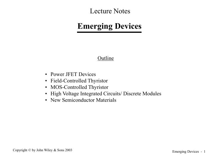
Lecture Notes Emerging Devices Outline • Power JFET Devices • Field-Controlled Thyristor • MOS-Controlled Thyristor • High Voltage Integrated Circuits/ Discrete Modules • New Semiconductor Materials
Power JFET I-V Characteristics • Power JFET is a normally-on device. Substantial current flows when gate- source voltage is equal to zero. • Opposite to BJTs, MOSFETs, and IGBTs which are normally-off devices.
JFET On and Off States • Channel pinched-off (closed) between drain and source. • Channel open between drain and source.
Bipolar Static Induction Transistor (BSIT) • Channel width and channel doping chosen so that at zero gate-source voltage, depletion layers of gate-channel junction pinch-off the channel. • Narrower channel than normally-on JFET. • Forward bias gate-channel junction to reduce depletion region width and open up channel. • Substantial current flow into gate.
JFET Switching Characteristics • Equivalent circuits of JFETS nearly identical to those of MOSFETs • Switching waveforms nearly identical to those of MOSFETs including values of various switching time intervals • JFET VGS starts at negative values and steps to zero at turn-on while MOSFET VGS starts at zero and steps to positive value at turn-on • FET on-state losses somewhat higher than for MOSFET - technology related not fundamental • Normally-off JFET (Bipolar static induction transistor or BSIT) switching characteristics more similar to those of BJT • Differences between BSIT and BJT observable mainly at turn-off 1. BSIT has no quasi-saturation region and thus only one current fall time (no current tailing) at turn-off. 2. Overall turn-off times of BSIT shorter than for BJT 3. Differences due to fact that BSIT has no in-line pn junction that can block sweep-out of excess carriers as does BJT
Field-Controlled Thyristor (FCT) Vertical Cross-section Circuit symbol • Sometimes termed a bipolar static induction thyristor (BSIThy).
FCT I-V Characteristics • FCT has a normally-on characteristic. • Can be made to have a normally-off characteristic. 1. Reduce channel width so that zero-bias depletion layer width of gate-channel junction pinches off channel 2. Then termed a bipolar static induction thyristor (BSIThy).
Physical Operation of FCT • Cascode switching circuit. • Implement a normally- off composite switch. • R1 and R2 insure that voltage across MOSFET not overly large. Permits use of low voltage-high current device. • FCT essentially a power JFET with an injecting contact at the drain • Injecting contact causes conductivity modulation of drain drift region and results in much lower on-state losses • At turn-off, gate draws large negative current similar to a GTO because of stored charge in drift region • FCT not a latching switch as is a GTO. FCT has no regenerative action. • FCT can be made a normally-off device by using narrow channel widths so that zero-bias width gate depletion layer pinchs off channel.
FCT Switching Characteristics •FCT switching waveforms qualitatively similar to thyristor or GTO including large negative gate current at turn-off. • FCT has gate-controlled turn-on and turn-off capabilities similar to GTO. • FCT switching times somewhat shorter than GTO. • Gate drive must be continuously applied to FCT because FCT has no latching characteristic. • FCT has much larger re-applied dv/dt rating than GTO because of lack of latching action. • FCT hasdi/dt limits because of localized turn-on and then expansion of turned-on region across entire device cross-section.
JFET-Based Devices Vs Other Power Devices • Blocking voltage capability of JFETs comparable to BJTs and MOSFETs. • JFET on-state losses higher than MOSFETs - technology limitation. • Switching speeds of normally-on JFET somewhat slower than those of MOSFET - technology limitation. • BSIT switching times comparable to BJTs - in principle should be faster because of lack of in- line pn junction trapping stored charge at turn-off. • No second breakdown in normally-on JFETs, similar to MOSFETs. • BSITs and BSIThy have and possibly limitations. • JFET-based power devices much less widely used because of normally-on characteristic. This has also slowed research and development efforts in these devices compared to other devices.
P-MCT (P-type MOS-controlled Thyristor Unit cell vertical cross-section • Complete MCT composed of tens of thousands of identical cells connected in parallel. • P-designation refers to doping of the lightly-doped P- layer which contains the depletion layer of the blocking junction. • Note that ON and OFF FETs are positioned at the anode end of the device.
P-MCT Equivalent Circuit & Circuit Symbol P-MCT equivalent circuit P-MCT circuit symbol • P-MCT used with anode grounded. • Gate-anode voltage is input drive voltage. • Use P-MCT in circuits with negative voltages.
N-MCT (N-type MOS-controlled Thyristor Vertical cross-section of N-MCT unit cell • N-MCT composed of thousands of cells connected electrically in parallel. • N-designation refers to the N- layer which contains the depletion layer of the blocking junction. • Note that the ON and OFF FETs are positioned at the cathode end of the device.
N-MCT Equivalent Circuit & Circuit Symbol N-MCT equivalent circuit N-MCT circuit symbol • N-MCT used with cathode grounded. • Gate-cathode voltage is input drive voltage. • Use N-MCT in circuits with positive voltages.
Gate-controlled Turn-on of MCTs • Turn on MCT by turning on the ON-FET • Positive gate-cathode voltage for N-MCT • Negative gate-anode voltage for P-MCT • These polarities of gate voltage automatically keep the OFF-FET in cutoff. • ON-FET delivers base current to the low-gain BJT in the thyristor equivalent circuit and activates that BJT. • PNP transistor in the N-MCT • NPN transistor in the P-MCT • Low-gain transistor activates the higher gain transistor and thyristor latches on. • Once higher gain transistor, which is in parallel with ON-FET is activated, current is shunted from ON-FET to the BJT and the ON-FET carries very little current in the MCT on-state. • Only 5-10% of the cells have an ON-FET. • Cells are close-packed. Within one excess carreier diffusion length of each other. • Adjacent cells without an ON-FET turned on via diffusion of excess carriers from turned-on cell.
Gate-controlled Turn-off of MCTs • Turn MCT off by turning on the OFF-FET • Negative gate-cathode for the N-MCT • Positive gate-anode voltage for the P-MCT • These gate voltage polarities automatically keep the ON-FET in cut-off. • OFF-FET shunts base current away from the higher gain BJT in the thyristor equivalent circuit and forces it to cut-off. • NPN transistor in the N-MCT. • PNP transistor in the P-MCT. • Cut-off of higher gain BJT then forces low-gain BJT into cut-off. • Every MCT cell has an OFF-FET. • OFF-FET kept activated during entire MCT off-state to insure no inadvertent activation of the thyristor.
Maximum Controllable Anode Current • If drain-source voltage of OFF-FET reaches approximately 0.7 V during turn-off, then MCT may remain latched in on-state. • Higher-gain BJT remains on if OFF-FET voltage drop, which is the base-emitter voltage of the BJT reaches 0.7 volts. • Thus maximum on-state current that can be turned off by means of gate control. • P-MCT have approximately three times larger gate-controlled anode current rating than a similar (same size and voltage rating) N-MCT. • OFF-FET of the P-MCT is an n-channel MOSFET which has three times larger channel mobility than the p-channel OFF-FET of the N-MCT.
Rationale of OFF-FET Placement P-MCT cross-section showing rationale for OFF-FET placement • Turning off the BJT with the larger value of amost effective way to break the latching condition a1 + a2 = 1 • BJT with the smaller base width has the larger value of a. • P-MCT ; PNP BJT has smaller base width • N-MCT ; NPN BJT has smaller base width • OFF-FET put in parallel with base- emitter of larger gain BJT so that OFF-FET shorts out base-emitter when the FET is activated.
MCT Switching Waveforms N-MCT Step-down Converter P-MCT Step-down Converter
MCT Operating Limitations • MCT safe operating area. Very conservatively estimated.
Dielectric Isolation • Dielectrically isolated tubs - SiO2 isolation and silicon thin film overgrowth. • Wafer bonding and subsequent wafer thinning.
Self-Isolation and Junction Isolation • Self-isolation - only feasible with MOSFET devices. • Junction isolation.
High-Voltage Low-Voltage Cross-overs • Field-crowding and premature breakdown. • Use of field shields to minimize field crowding problems at HV/LV cross-overs.
Smart or Intelligent Switch Using MOSFETs • Cross-sectional diagram of switch. • Circuit diagram
Smart Power Switch Using BJTs Cross-sectional view
High Voltage Integrated Circuits (HVICs) HVIC using junction isolation HVIC using self-isolation
Discrete Module Example - IXYS I3M IGBT Module • Intelligent isolated half-bridge • 200 A - 1080 V • Built-in protection and sensing of overcurrents, overvoltages, overtemperatures, short circuits. • Modules with only IGBTs and anti- parallel diodes available with ratings of 3300V - 1200A
IGCT - Integrated Gate Commutated Thyristor • Specially designed GTO with low inductance gate drive circuit • Ratings • Blocking voltage - 4500V • Controllable on-state current - 4000A • Average fwd current - 1200A • Switching times - 10µsec • Approximate gate drive circuit • Ion ≈ 500 A 10µsec • Ioff - full forward current 10 usec • Very low series inductance - 3 nH
Emitter Turn-off Thyristor • Performance similar to IGCTs • Advantages over IGCTs • Simpler drive circuit • Easier to parallel - MOSFETs in series with GTO have positive temperature coefficient • Series MOSFETs can be used for overcurrent sensing
Recent Advances/Benchmarks • Gallium arsenide • 600V GaAs Schottky diodes announced by Motorola. 250V available from IXYS • 3” GaAs wafers available • Silicon carbide • 3” wafers available from Cree Research - expensive • 600V -6A Schottky diodes available commercially - Infineon Technologies AG (Siemens spinoff) • Controlled switches also demonstrated • 1800V - 3A BJT with beta of 20 • 3100V - 12A GTO • Diamond • Polycrystalline diamond films of several micron thickness grown over large (square centimeters) areas • Simple device structures demonstrated in diamond films. • PN junctions • Schottky diodes