Download
1 / 43
430 likes | 524 Views
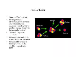
Fusion Nuclear Technology Development and the Role of CTF toward DEMO. Mohamed Abdou. Information Developed for the FESAC Development Pathway Panel (Fall 2002 / Winter 2003).

E N D
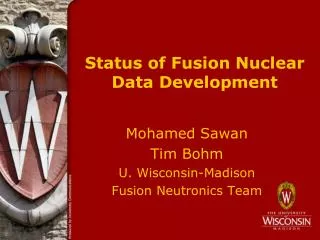
Fusion Nuclear Technology Development and the Role of CTF toward DEMO Mohamed Abdou Information Developed for the FESAC Development Pathway Panel (Fall 2002 / Winter 2003) With input from A. Ying, M. Ulrickson, D. K. Sze, S. Willms, F. Najmabadi, J. Sheffield, M. Sawan, C. Wong, R. Nygren, P. Peterson, S. Sharafat, R. Buende, N. Morley, L. Waganer, D. Petti, E. Cheng, M. Peng, and L. Cadwallader
What is CTF? • The idea of CTF is to build a small size, low fusion power DT plasma-based device in which Fusion Nuclear Technology experiments can be performed in the relevant fusion environment at the smallest possible scale, cost, and risk. - In MFE: small-size, low fusion power can be obtained in a low-Q plasma device. - Equivalent in IFE: reduced target yield and smaller chamber radius • This is a faster, much less expensive, less risky approach than testing in a large, ignited/high Q plasma device for which tritium consumption, and cost of operating to high fluence are very high (unaffordable!, not practical).
Fusion Nuclear Technology (FNT) Fusion Power & Fuel Cycle Technology FNT Components from the edge of the Plasma to TF Coils(Reactor “Core”) 1. Blanket Components 2. Plasma Interactive and High Heat Flux Components a. divertor, limiter b. rf antennas, launchers, wave guides, etc. 3. Vacuum Vessel & Shield Components Other Components affected by the Nuclear Environment 4. Tritium Processing Systems 5. Instrumentation and Control Systems 6. Remote Maintenance Components 7. Heat Transport and Power Conversion Systems
Notes on FNT: • The Vacuum Vessel is outside the Blanket (/Shield). It is in a low-radiation field. • Vacuum Vessel Development for DEMO should be in good shape from ITER experience. • The Key Issues are for Blanket / PFC. • Note that the first wall is an integral part of the blanket (ideas for a separate first wall were discarded in the 1980’s). The term “Blanket” now implicitly includes first wall. • Since the Blanket is inside of the vacuum vessel, many failures (e.g. coolant leak from module) require immediate shutdown and repair/replacement. Adaptation from ARIES-AT Design
Summary of Critical R&D Issues for Fusion Nuclear Technology • D-T fuel cycle tritiumself-sufficiency in a practical system • depends on many physics and engineering parameters / details: e.g. fractional burn-up in plasma, tritium inventories, FW thickness, penetrations, passive coils, etc. • 2. Tritium extraction and inventory in the solid/liquid breeders under actual operating conditions • 3.Thermomechanicalloadings and response of blanket and PFC components under normal and off-normal operation • 4. Materials interactions and compatibility • 5. Identification and characterization of failure modes, effects, and rates in blankets and PFC’s • 6. Engineering feasibility and reliability of electric (MHD) insulators and tritium permeation barriers under thermal / mechanical / electrical / magnetic / nuclear loadings with high temperature and stress gradients • 7. Tritium permeation, control and inventory in blanket and PFC • 8. Lifetime of blanket, PFC, and other FNT components • 9. Remote maintenance with acceptable machine shutdown time.
What is DEMO? (Excerpts from FESAC Panel Interim Report) The goal of the plan is operation of a US demonstration power plant (Demo), which will enable the commercialization of fusion energy. The target date is about 35 years. Early in its operation the Demo will show net electric power production, and ultimately it will demonstrate the commercial practicality of fusion power. It is anticipated that several such fusion demonstration devices will be built around the world. In order for a future US fusion industry to be competitive, the US Demo must: a. be safe and environmentally attractive, b. extrapolate to competitive cost for electricity in the US market, as well as for other applications of fusion power such as hydrogen production, c. use the same physics and technology as the first generation of competitive commercial power plants to follow, and d. ultimately achieve availability of ~ 50%, and extrapolate to commercially practical levels.
R&D Tasks to be Accomplished Prior to Demo 1) Plasma - Current Drive/Steady State - Confinement/Burn - Edge Control - Disruption Control 2) Plasma Support Systems - Superconducting Magnets - Fueling - Heating 3) Fusion Nuclear Technology Components and Materials [Blanket, First Wall, High Performance Divertors, rf Launchers] - Materials combination selection and configuration optimization - Performance verification and concept validation - Show that the fuel cycle can be closed (tritium self-sufficiency) - Failure modes and effects - Remote maintenance demonstration - Reliability growth - Component lifetime 4) Systems Integration Where Will These Tasks be Done?! • Burning Plasma Facility (ITER) and other plasma devices will address 1, 2, & much of 4 • Fusion Nuclear Technology (FNT) components and materials require dedicated fusion facility(ies) parallel to ITER (prior to DEMO)
International studies and experts have concluded that extensive testing of fusion nuclear components in FUSION testing facilities is REQUIRED prior to DEMO --Non-fusion facilities cannot fully resolve any of the critical issues for blankets or PFC’s --There are critical issues for which no significant information can be obtained from testing in non-fusion facilities (An example is identification and characterization of failure modes, effects and rates) --The Feasibility of Blanket/PFC Concepts can NOT be established prior to testing in fusion facilities Note: Non-fusion facilities can and should be used to narrow material and design concept options and to reduce the costs and risks of the more costly and complex tests in the fusion environment. Extensive R&D programs on non-fusion facilities should start now.
Key Fusion Environmental Conditions for Testing Fusion Nuclear Components • Neutrons (fluence, spectrum, spatial and temporal gradients) • -Radiation Effects • (at relevant temperatures, stresses, loading conditions) • - Bulk Heating • - Tritium Production • - Activation • Heat Sources (magnitude, gradient) • - Bulk (from neutrons) • - Surface • Particle Flux (energy and density, gradients) • Magnetic Field (3-component with gradients) • - Steady Field • - Time-Varying Field • Mechanical Forces • -Normal • - Off-Normal • Thermal/Chemical/Mechanical/Electrical/Magnetic Interactions • Synergistic Effects • -Combined environmental loading conditions • - Interactions among physical elements of components
FNT Requirements for Major Parameters for Testing in Fusion Facilities with Emphasis on Testing Needs to Construct DEMO Blanket - These requirements have been extensively studied over the past 20 years, and they have been agreed to internationally (FINESSE, ITER Blanket Testing Working Group, IEA-VNS, etc.) - Many Journal Papers have been published (>35) - Below is the Table from the IEA-VNS Study Paper (Fusion Technology, Vol. 29, Jan 96) a - Prototypcial surface heat flux (exposure of first wall to plasma is critical) b - If steady state is unattainable, the alternative is long plasma burn with plasma duty cycle >80% c - Note that the fluence is not an accumulated fluence on “the same test article”; rather it is derived from testing “time” on “successive” test articles dictated by “reliability growth” requirements
Stages of FNT Testing in Fusion Facilities D E M O Component Engineering Development & Reliability Growth Design Concept & Performance Verification Fusion “Break-in” Stage: I II III Required Fluence (MW-y/m2) ~ 0.3 1 - 3 > 4 - 6 Size of Test Article Sub-Modules Modules/ Sectors Modules • Initial exploration of performance in a fusion environment • Calibrate non-fusion tests • Effects of rapid changes in properties in early life • Initial check of codes and data • Develop experimental techniques and test instrumentation • Narrow material combination and design concepts • 10-20 test campaigns, each is 1-2 weeks • Tests for basic functions and phenomena (tritium release / recovery, etc.), interactions of materials, configurations • Verify performance beyond beginning of life and until changes in properties become small (changes are substantial up to ~ 1-2 MW · y/m2) • Data on initial failure modes and effects • Establish engineering feasibility of blankets (satisfy basic functions & performance, 10 to 20% of lifetime) • Select 2 or 3 concepts for further development • Identify failure modes and effects • Iterative design / test / fail / analyze / improve programs aimed at improving reliability and safety • Failure rate data: Develop a data base sufficient to predict mean-time-between-failure with sufficient confidence • Obtain data to predict mean-time-to-replace (MTTR) for both planned outage and random failure • Develop a data base to predict overall availability of FNT components in DEMO
Critical Factors in Deciding where to do Blanket / PFC / FNT Testing • Tritium Consumption / Supply Issue • Reliability / Maintainability / Availability Issue • Cost • Risk • Schedule Analysis of these factors shows that: Blanket/FNT Fusion Testing must be in a small-size, small-power DT fusion device.
Blanket/FNT Fusion Testing is Not Practical in Large-Power, Large-Size Devices • The FNT Testing Requirements are Fusion Power only 20-30 MW Over about 10m2 of surface area (with exposure to plasma) With Steady State Plasma Operation (or plasma cycle >80%) Testing Time on successive test articles equivalent to neutron fluence of 6 MW • y/m2 • Tritium Consumption / Tritium Supply issue dictates that any large-power fusion facility that performs FNT testing must internally breed all (or most) of its own tritium • CONTRADICTIONS of Large-Power Device (>100 MW fusion Power): The facility used to “test” the breeding technology must itself be a “user” of breeding technology • FNT Testing involves large RISKS to the fusion testing device - unvalidated technology with direct exposure to plasma - frequent failures are expected - considerable amounts of tritium and activated materials - These risks are much greater for large power devices because of the much larger area for tritium breeding • Cost - Frequent failures will require frequent replacements:COST of “replacements” will be much higher for the larger power, larger area devices - COST of operation to higher fluence is larger for larger devices
Where to do Blanket/PFC/FNT Fusion Testing? Options / Scenarios 1. ITER (FEAT) - Not possible with current design (Blanket Tests in ITER are important but limited to some functional tests) 2. Modified ITER (Redesign to satisfy FNT Testing Parameters) - Too expensive: as a minimum, think of $5B difference between EDA & FEAT - Issues of tritium consumption, risks 3. Defer to DEMO - Unthinkable! (Unvalidated technology in DEMO?!) - Not Practical, Very Expensive, Huge Risks (All the contradictions of using large-power, large-size device for FNT testing) 4. Add Small Size, Small Power Device for FNT Testing (CTF) Lowest cost, least risk, fastest approach a – CTF parallel to ITER b – CTF delayed start relative to ITER
ITER-FEAT as designed can NOT perform most of the testing of fusion nuclear components - ITER (FEAT) has been designed as a burning plasma experiment - The changes in design from ITER-EDA to ITER-FEAT have made ITER not a suitable facility for most of FNT testing - ITER-FEAT Parameters do not satisfy FNT testing requirements: • Neutron wall load: 0.55 MW/m2 (compared to required 1-2 MW/m2) • Neutron fluence: 0.1 MW·y/m2 (compared to required >6 MW·y/m2) • Plasma duty cycle makes it impossible to adequately perform the FNT testing mission - FNT testing requires steady state (or at least plasma duty cycle > 80%) - ITER-FEAT has short plasma burn (400S), long dwell time (1200S) resulting in a plasma duty cycle of 25% - The ITER-FEAT short burn/long dwell plasma cycle does not even enable temperature equilibrium in test modules, a fundamental requirement for many tests (most FNT tests are highly temperature dependent)
Mode of Plasma Operation in ITER-FEAT Rule Out Most of FNT Testing • This issue was investigated extensively in several studies including the ITER Test Blanket Working Group in both ITER-CDA and ITER-EDA, IEA-VNS. The conclusion reached: need steady state (or if unattainable, long burn/short dwell with plasma duty cycle >80%). • Extensive Investigation of Blanket Testing Requirements using detailed engineering scaling to preserve phenomena, etc. show that: plasma burn time (tb) > 3 c plasma dwell time (td) < 0.05 c Where cis a characteristic time constant (for a given phenomena) • Characteristic time constants for various responses/phenomena in the blanket range from a few seconds to a few hours (even days for some phenomena). See Tables in Appendix. - Thus the burn time needs to be hours and the dwell time needs to be a few seconds. • Example of Difficulty: In ITER-FEAT scenario of 400 s burn and 1200 s dwell time, even temperature equilibrium can not be attained. Most critical phenomena in the blanket have strong temperature dependence. Tests for phenomena such as tritium release and recovery, failure modes, etc. can yield the wrong answer
Example of many calculations in the literature of the adverse effects of low plasma cycle* on the usefulness of FNT tests First unit cell breeder temperature response (burn time = 1000 s, dwell time = 500 s) *Not long enough burn time and not short enough dwell time
Tritium Consumption in Large and Small Power DT Devices AND Tritium Supply Issue AND Impact on the Path to FNT Development Note: Projections of world tritium supply available to fusion for various scenarios were generated by Scott Willms, including information from Paul Rutherford’s 1998 memo on “Tritium Window”, and input from M. Abdou and D. Sze.
Projections for World Tritium Supply Available to Fusion Reveal Serious Problems 30 25 Candu Supply 20 w/o Fusion Projected Ontario (OPG) Tritium Inventory (kg) 15 World Max. tritium supply is 27 kg 10 Tritium decays at a rate of 5.47% per year 5 0 1995 2000 2005 2010 2015 2020 2025 2030 2035 2040 2045 Year • Tritium Consumption in a DT facility burns tritium at a rate of: 55.8 kg/yr per 1000 MW of fusion power (Huge, Unprecedented!!) • Current Tritium cost is $30 million/kg. Fission reactors can produce only a few kg per year at $200 M/kg!! It takes tens of fission reactors to supply one fusion reactor. Conclusion There is no external tritium supply to do blanket/FNT testing in a large power DT fusion device. Blanket/FNT development must be in a small fusion power device.
Separate Devices for Burning Plasma and FNT Development, i.e. ITER (FEAT) + CTF is more Cost Effective and Faster than a Single Combined Device(to change ITER design to satisfy FNT testing requirements is very expensive and not practical) FACTS - World Maximum Tritium Supply (mainly CANDU) available for Fusion is 27 kg - Tritium decays at 5.47% per year - Tritium cost now is $30M / kg. More tritium will cost $200M / kg. Conclusion: - There is no external tritium supply to do FNT testing development in a large power DT fusion device. FNT development must be in a small fusion power device.
Projections for World Tritium Supply Available to Fusion for Various Scenarios (Willms, et al) See calculation assumptions in Table S/Z • World Tritium Supply would be Exhausted by 2025 if ITER were to run at 1000 MW fusion power with 10% availability • Large Power DT Fusion Devices are not practical for blanket/PFC development. • We need 5-10 kg of tritium as “start-up” inventory for DEMO (can be provided from CTF operating with TBR > 1 at later stage of operation) • Blanket/PFC must be developed prior to DEMO (and we cannot wait very long for blanket/PFC development even if we want to delay DEMO).
Table S/Z (data used in Fig. for Tritium Supply and Consumption Calculations) Tritium Supply Calculation Assumptions: • Ontario Power Generation (OPG) has seven of twenty CANDU reactors idled • Reactors licensed for 40 years • 15 kg tritium in 1999 • 1999 tritium recovery rate was 2.1 kg/yr • Tritium recovery rate will decrease to 1.7 kg/yr in 2005 and remain at this level until 2025 • After 2025 reactors will reach their end-of-life and the tritium recovery rate will decrease rapidly • OPG sells 0.1 kg/yr to non-ITER/VNS users • Tritium decays at 5.47 % / yr It is assumed that the following will NOT happen: • Extending CANDU lifetime to 60 years • Restarting idle CANDU’s • Processing moderator from non-OPG CANDU’s (Quebec, New Brunswick) • Building more CANDU’s • Irradiating Li targets in commercial reactors (including CANDU’s) • Obtaining tritium from weapons programs of “nuclear superpowers” • Premature shutdown of CANDU reactors
Table S/Z (cont’d) (data used in Fig. for Tritium Supply and Consumption Calculations cont’d) ITER-FEAT Assumptions: • Construction starts in 2004 and lasts 10 years • There are four years of non-tritium operation • This is followed by 16 years of tritium operation. The first five years use tritium at a linearly increasing rate reaching 1.08 kg T used per year in the fifth year. Tritium usage remains at this level for the remainder of tritium operations. • There is no tritium breeding (TBR=0) • There is no additional tritium needed to fill materials and systems CTF Assumptions: • Begins burning tritium in 2017 • 5 yr, 100 MW, 20% availability, TBR 0.6 • 5 yr, 120 MW, 30% availability, TBR 1.15 • 10 yr, 150 MW, 30% availability, TBR 1.3
Reliability / Maintainability / Availability Critical Development Issues Unavailability = U(total) = U(scheduled) + U(unscheduled) This you design for This can kill your DEMO and your future Scheduled Outage: Planned outage (e.g. scheduled maintenance of components, scheduled replacement of components, e.g. first wall at the end of life, etc.). This tends to be manageable because you can plan scheduled maintenance / replacement operations to occur simultaneously in the same time period. Unscheduled Outage: (This is a very challenging problem) Failures do occur in any engineering system. Since they are random they tend to have the most serious impact on availability. This is why “reliability/availability analysis,” reliability testing, and “reliability growth” programs are key elements in any engineering development.
Availability (Due to Unscheduled Events) Availability: = represents a component (Outage Risk) = (failure rate) • (mean time to repair) = MTBF = mean time between failures = 1/failure rate MTTR = mean time to repair • A Practical Engineering System must have: 1. Long MTBF: have sufficient reliability - MTBF depends on reliability of components. One can estimate what MTBF is NEEDED from “availability allocation models” for a given availability goal and for given (assumed) MTTR. But predicting what MTBF is ACHIEVEABLE requires real data from integrated tests in the fusion environment. 2. Short MTTR: be able to recover from failure in a short time - MTTR depends on the complexity and characteristics of the system (e.g. confinement configurations, component blanket design and configuration, nature of failure). Can estimate, but need to demonstrate MTTR in fusion test facility.
An Example Illustration of Achieving a Demo Availability of 49% (Table based on information from J. Sheffield’s memo to the Dev Path Panel) Assuming 0.2 as a fraction of year scheduled for regular maintenance. Availability = 0.8* [1/(1+0.624)] = 0.49
The reliability requirements on the Blanket/FW (in current confinement concepts that have long MTTR > 1 week) are most challenging and pose critical concerns. These must be seriously addressed as an integral part of the R&D pathway to DEMO. Impact on ITER is predicted to be serious. It is one of the key DRIVERS for CTF. A = Expected with extensive R&D (based on mature technology and no fusion-specific failure modes C = Potential improvements with aggressive R&D
Reliability/Availability is a challenge to fusion, particularly blanket/PFC, development • Fusion System has many majorcomponents (TFC, PFC, plasma heating, vacuum vessel, blanket, divertor, tritium system, fueling, etc.) - Each component is required to have high availability • All systems except the reactor core (blanket/PFC) will have reliability data from ITER and other facilities • There is NO data for blanket/PFC (we do not even know if any present blanket concept is feasible) • Estimates using available data from fission and aerospace for unit failure rates and using the surface area of a tokamak show: PROBABLE MTBF for Blanket ~ 0.01 to 0.2 yr compared to REQUIRED MTBF of many years Aggressive “Reliability Growth” Program We must have an aggressive “reliability growth” program for the blanket / PFC (beyond demonstrating engineering feasibility) 1) All new technologies go through a reliability growth program 2) Must be “aggressive” because extrapolation from other technologies (e.g. fission) strongly indicates we have a serious CHALLENGE
Reference: M. Abdou et. al., "FINESSE A Study of the Issues, Experiments and Facilities for Fusion Nuclear Technology Research & Development, Chapter 15 (Figure 15.2-2.) Reliability Development Testing Impact on Fusion Reactor Availability", Interim Report, Vol. IV, PPG-821, UCLA,1984. It originated from A. Coppola, "Bayesian Reliability Tests are Practical", RADC-TR-81-106, July 1981. “Reliability Growth” Upper statistical confidence level as a function of test time in multiples of MTBF for time terminated reliability tests (Poisson distribution). Results are given for different numbers of failures. Example, To get 80% confidence in achieving a particular value for MTBF, the total test time needed is about 3 MTBF (for case with only one failure occurring during the test). TYPICAL TEST SCENARIO
Schedule now in 2002 2007 2017 2027 2037 2047 2057 Schedule back in 1995 ITER ITER-FEAT BPP Phase 1 EPP Phase 2 VNS CTF Legend for Demo Design Construction Operation Numbers refer to Fluence values in MW•y/m2 Scenarios for major fusion devices leading to a DEMO
0.654 III: ITER +VNS 0.492 This assumes that the divertor has availability similar to blanket system availability, & that combined availability of all other major Demo components = 60% II: ITER BPP +VNS Blanket System Availability DEMO Reactor Availability 0.360 IV: ITER + delayed VNS 0.189 I: ITER only (Schedule back in 1995) 2013 2017 2021 2025 2029 2033 2037 (Schedule now in 2002) Calendar year Note: ITER in Scenarios I, III and IV assumes fluence of 1.1 MW.y/m2 (ITER-FEAT 1st phase has 0.1 MW.y/m2) 0.4 MTTR = 1 month 12 test modules 1 failure during the test 0.3 Experience factor =0.8 0.2 0.1 0.0 2006 2010 2014 2018 2022 2026 2030 DEMO reactor availability obtainable with 80% confidence for different testing scenarios, MTTR = 1 month
Conclusions on Blanket and PFC Reliability Growth • Blanket and PFC tests in ITER alone cannot demonstrate DEMO availability higher than 4% • Blanket and PFC testing in VNS (CTF) allows DEMO blanket system and PFC system availability of > 50%, corresponding to DEMO availability > 30% Recommendations on Availability/Reliability Growth Strategy and Goals - Set availability goal for initial operation of DEMO of ~ 30% (i.e. defer some risk) - Operate CTF and ITER in parallel, together with other facilities, as aggressively as possible - Realize that there is a serious decision point with serious consequences based on results from ITER and CTF • If results are positive proceed with DEMO • If not, then we have to go back to the drawing board
Component Technology Facility (CTF) MISSION The mission of CTF is to test, develop, and qualify Fusion Nuclear Technology Components (fusion power and fuel cycle technologies) in prototypical fusion power conditions. The CTF facility will provide the necessary integrated testing environment of high neutron and surface fluxes, steady state plasma (or long pulse with short dwell time), electromagnetic fields, large test area and volume, and high neutron fluence. The testing program and CTF operation will demonstrate the engineering feasibility, provide data on reliability / maintainability / availability, and enable a “reliability growth” development program sufficient to design, construct, and operate blankets, plasma facing and other FNT components for DEMO.
CTF MISSION is integrated testing and development of fusion power and fuel cycle technologies (FNT) in prototypical fusion power conditions Scope of Testing in CTF • Information Obtained from Basic Device • Divertor Operation • Heating and Current Drive Systems PFC • Partial to full breeding, high temperature blanket (staged operation and breeding) • Neutronics and Shielding • Tritium Fuel Cycle • Demonstration of Remote Maintenance Operations • through frequent changeout of various test articles • through repairs and changeout on the basic device • Testing in Specialized Test Ports (and substantial FW coverage at later stages of operation) • MaterialsTest Module • Material Properties Specimen matrix • Blanket Test Modules • Screening Tests • Performance Verification • Reliability Growth • Divertor Test Modules • Engineering Performance • Design Improvements and Advanced Divertor Testing • Current Drive and Heating Launchers • NeutronicsTest Sector • Safety Aspects of the Test Program • TritiumProcessing
2005 2010 2015 2020 2025 2030 2035 2040 ITER Construction & Commission Operation Phase 1a Phase 1 b Operation DT Phase 2 Design Exploration Construction Conceptual Design Engineering Feasibility CTF Component Reliability Engineering Design Demo Design Construct Operate Proposed CTF Timeline Time line for ITER is taken from K. Lackner’s presentation at SOFT, 2002
Are there Good Design Options for CTF? • A key point in the rationale behind CTF is to design a small size, small fusion power (~100 MW), yet achieve a high neutron wall load and steady state plasma operation. • This can be achieved in MFE by using highly driven plasma (low-Q plasma ~ 1-2). • Several good design options for CTF look attractive. - Explored in literature since FINESSE study in 1985. - New promising design options presented to FESAC DEVELOPMENT Pathway Panel - Typically, they are about 100MW fusion power, or less, with first wall surface area of 60-120 m2, reasonably low cost. • The fusion physics and engineering communities need to jointly explore in more detail the options for CTF: e.g. - ST, low-A, standard-A - physics and engineering details
Summary A CREDIBLE Plan for DT Fusion Development MUST include a CREDIBLE Plan for Blanket/PFC Development • The FEASIBILITY, Operability, and Reliability of Blanket/PFC systems cannot be established without testing in fusion facilities • The fusion testing requirements for blanket/PFC are: - NWL > 1 MW/m2, steady state, test area >10m2, test volume >5 m3 - Fluence Requirements: > 6 MW•y/m2 Engineering Feasibility Phase: 1 – 3 MW•y/m2 (concept performance verification and selection) Engineering Development & Reliability Growth Phase: >4 MW•y/m2 (not an accumulated fluence on a test article; it is “accumulated test time” on successively improved test articles) • Tritium Supply considerations are a critical factor in developing a credible strategy for fusion testing and development of blanket/PFC - The world maximum tritium supply (from CANDU) over the next 40 years is 27 kg. This tritium decays at 5.47% per year. Cost is high ($30M-$200M/kg) - Remember: A DT facility with 1000 MW fusion power burns tritium at a rate of 55.8 kg/yr. Therefore, a large power DT facility must breed its own tritium. (It is ironic that our major problem is “tritium fuel supply”, while the fundamental premise of Fusion is “inexhaustible” energy source)
Summary Cont’d Options for “Where” to do Blanket/PFC Developments were evaluated: 1 – ITER(FEAT): Not Suitable for Most Tests • Low fluence, short plasma burn time/long dwell time, low wall load do not provide the required capability 2 – MODIFIED ITER: Too Expensive, Too Risky • Requires complete redesign. Very Expensive (Think of ITER-EDA cost plus more) • Tritium is not available to run the large-power ITER for high fluence • For Modified ITER to have its own tritium breeding blanket with TBR ~1 is very risky and extremely expensive (building unvalidated blanket over 1000 m2 is costly, frequent blanket failures require costly replacements) 3 – DEMO: “Unthinkable” • Deferring Blanket/PFC development until DEMO is “unthinkable” because: A – All the problems indicated for Modified ITER above (same mistake of doing FNT testing in large power DT device). Plus there is not much external tritium supply left to start DEMO. B – This is not a DEMO: a minimum requirement for DEMO is to have at least one validated concept for each component.
Summary Cont’d So, we have a Serious Problem! So, what to do? - Think of What Fission Reactor Developers did as an example: They built small-power testing reactors (10-100 MW), but with prototypical local conditions. (They were lucky!!) - Take advantage of the fact that our good fusion engineers have developed and utilized “engineering scaling” to reduce the FNT testing requirements to only 10-20 MW of fusion power with about 10 m2 test area (5 m3 test volume)
Summary Cont’d Attractive Logical Solution • Build a small size, low-fusion power DT plasma-based device in which Fusion Nuclear Technology experiments can be performed in the relevant fusion environment at the smallest possible scale and cost. - In MFE: small-size, low fusion power can be obtained in a driven low-Q plasma device. - Equivalent in IFE: Lower target yield and smaller chamber radius. • This is a faster, much less expensive and less risky approach than testing in a large, ignited/high-Q plasma device for which tritium consumption, and cost of operating to high fluence are very high and the risk is too great.