Download
1 / 48
480 likes | 619 Views
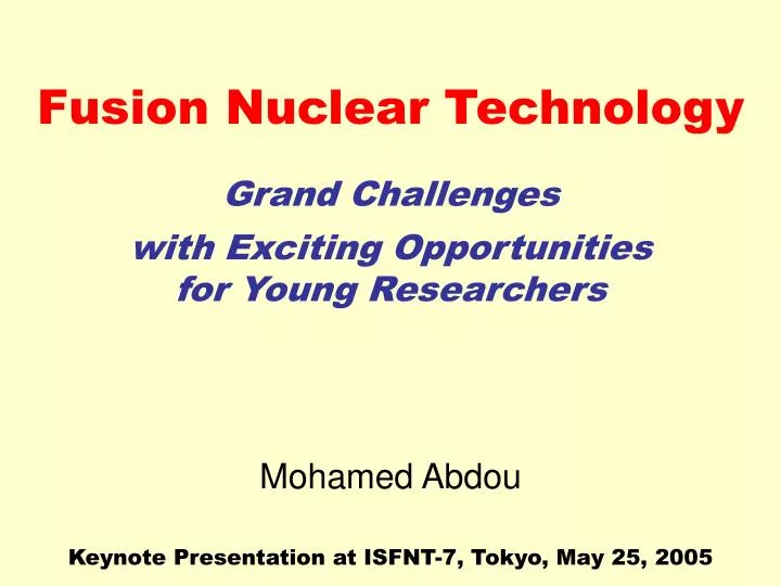
Fusion Nuclear Technology. Grand Challenges. with Exciting Opportunities for Young Researchers. Keynote Presentation at ISFNT-7, Tokyo, May 25, 2005. Mohamed Abdou. Acknowledgements.

E N D
Fusion Nuclear Technology Grand Challenges with Exciting Opportunities for Young Researchers Keynote Presentation at ISFNT-7, Tokyo, May 25, 2005 Mohamed Abdou
Acknowledgements • Heartfelt thanks to the ISFNT-7 organizers (particularly the Chairman, Dr. Masahiro Seki) for their dedicated efforts in planning a very successful conference. Thanks also for the invitation to give this presentation. • I solicited input on advances and challenges of FNT from many experts and leaders of FNT around the world. I truly appreciate their thoughtful and insightful responses. Siegfried Malang Luciano Giancarli Masato Akiba Alice Ying Neil Morley Lorenzo Boccaccini Dai-Kai Sze Shahram Sharafat Steve Zinkle Takeo Muroga Akira Kohyama Sergey Smolentsev Akio Sagara Mohamed Sawan Nasr Ghoniem Scott Willms Clement Wong Paola Batistoni Brad Merrill Dave Petti Lee Cadwallader Phil Sharpe Jeff Brooks Ahmad Hassanein
Fusion Nuclear Technology (FNT) Fusion Power & Fuel Cycle Technology FNT Components and Materials from the edge of the Plasma to TF Coils(Reactor “Core”) 1. Blanket Components 2. Plasma Interactive and High Heat Flux Components a. divertor, limiter b. rf antennas, launchers, wave guides, etc. 3. Vacuum Vessel & Shield Components Other Components affected by the Nuclear Environment 4. Tritium Processing Systems 5. Instrumentation and Control Systems 6. Remote Maintenance Components 7. Heat Transport and Power Conversion
Reflections on Progress and Challenges of the Last Decade • During the past 10 years, research on FNT made a lot of progress in several areas, but also encountered some disappointments—some issues proved more challenging than previously thought • The World’s Fusion Effort Focused on ITER: • Most extensive engineering effort to date • ITER Engineering design clearly brought about the importance of FNT • Despite the fact that power load, fluence and temperature in ITER are modest, it took much time and effort to understand and conceive acceptable solutions to FNT design issues (first wall, divertor, tritium, etc.) Conclusions: • Successful ITER operation and an effective ITER Test Blanket Module (TBM) still require important FNT R&D • FNT for devices beyond ITER is very challenging & requires focus & innovation ITER is the Beginning, not the End
Challenging Fusion Nuclear Technology Issues • Tritium Supply & Tritium Self-Sufficiency • High Power Density • High Temperature • MHD for Liquid Breeders / Coolants • Tritium Control (Permeation) • Reliability / Availability • Testing in Fusion Facilities
Projections for World Tritium Supply Available to Fusion Reveal Serious Problems 30 25 CANDU Supply 20 w/o Fusion Projected Ontario (OPG) Tritium Inventory(kg) 15 World Max. tritium supply is 27 kg 10 Tritium decays at a rate of 5.47% per year 5 0 2000 2010 2020 2030 2040 Year Tritium Consumption in Fusion is HUGE! Unprecedented! 55.8 kg per 1000 MW fusion power per year Production & Cost: CANDU Reactors:27 kg from over40 years, $30M/kg (current) Fission reactors:2–3 kg per year. It takes tens of fission reactors to supply one fusion reactor. $84M-$130M per kg, per DOE Inspector General* *DOE Inspector General’s Audit Report, “Modernization of Tritium Requirements Systems”, Report DOE/IG-0632, December 2003, available at www.ig.doe.gov/pdf/ig-0632.pdf
World Tritium Supply Would be Exhausted by 2025 if ITER Were to Run at 1000 MW at 10% Availability 30 25 CANDU Supply 20 w/o Fusion Projected Ontario (OPG) Tritium Inventory (kg) 15 1000 MW Fusion, 10% Avail, TBR 0.0 10 ITER-FEAT (2006 start construction) 5 0 2040 2000 2010 2020 2030 Year • Availability of external tritium supply for continued fusion development beyond ITER first phase is an issue • Large power D-T facilities must breed their own tritium(this is why ITER’s extended phase was planned to include the installation of a tritium breeding blanket) • Blanket development and ITER-TBM are necessary in the near term to allow continued development of D-T fusion
Tritium self-sufficiency condition:Λa > Λr Λr = Required tritium breeding ratio Λr is 1 + G, where G is the margin required to account for tritium losses, radioactive decay, tritium inventory in plant components, and supply inventory for start-up of other plants. Λris dependent on many system physics and technology parameters. Λa = Achievable tritium breeding ratio Λa is a function of technology, material and physics.
Λa = Achievable tritium breeding ratio Λa is a function of technology, material and physics. • FW thickness, amount of structure in the blanket, blanket concept. 30% reduction in Λa could result from using 20% structure in the blanket. (ITER detailed engineering design is showing FW may have to be much thicker than we want for T self sufficiency) • Presence of stabilizing/conducting shell materials/coils for plasma control and attaining advanced plasma physics modes • Plasma heating/fueling/exhaust, PFC coating/materials/geometry • Plasma configuration (tokamak, stellerator, etc.) Integral neutronics experiments in Japan and the EU showed that calculations consistently OVERESTIMATEexperiments by an average factor of ~ 1.14 Analysis* of current worldwide FW/Blanket concepts shows that achievable TBR Λa ≤ 1.15 * See, for example, Sawan and Abdou (this conference)
DT plasma PFC Blanket Dynamic fuel cycle models were developed to calculate time-dependent tritium flow rates and inventoriesSuch models are essential to predict the required TBR (Dynamic Fuel Cycle Modelling: Abdou/Kuan et al. 1986, 1999) Simplified Schematic of Fuel Cycle To new plants Fueling system T storage and management Startup Inventory Impurity separation and Isotope separation system Exhaust Processing (primary vacuum pumping) T processing for blanket and PFC depends on design option T waste treatment
Current physics and technology concepts lead to a “narrow window” for attaining Tritium self-sufficiency Fusion power 1.5GW Reserve time 2 days Waste removal efficiency 0.9 (See paper for details) td = doubling time Required TBR td=1 yr Max achievable TBR ≤ 1.15 td=5 yr td=10 yr “Window” for Tritium self sufficiency Fractional burn-up [%]
Physics and Technology R&D needs to assess the potential for achieving “Tritium Self-Sufficiency” • Establish the conditions governing the scientific feasibility of the D-T cycle, i.e., determine the “phase-space” of plasma, nuclear, material, and technological conditions in which tritium self-sufficiency can be attained • The D-T cycle is the basis of the current world plasma physics and technology program. There is only a “window” of physics and technology parameters in which the D-T cycle is feasible. We need to determine this “window.” (If the D-T cycle is not feasible the plasma physics and technology research would be very different.) • Examples of questions to be answered: • Can we achieve tritium fractional burn-up of >5%? • Can we allow low plasma-edge recycling? • Are advanced physics modes acceptable? • Is the “temperature window” for tritium release from solid breeders sufficient for adequate TBR? • Is there a blanket/material system that can exist in this phase-space?
R&D for Tritium Self-Sufficiency (cont’d) 2. Develop and test FW/Blankets/PFC that can operate in the integrated fusion environment under reactor-relevant conditions • The ITER Test Blanket Module (TBM) is essential for experimental verification of several principles necessary for assessing tritium self-sufficiency 3. R&D on FW/Blanket/PFC and Tritium Processing Systems that emphasize: • Minimizing Tritium inventory in components • “Much faster” tritium processing system, particularly processing of the “plasma exhaust” • Improve reliability of tritium-producing (blanket) and tritium processing systems 4. R&D on physics concepts that improve the tritium fractional burn-up in the plasma to > 5%
Need for High Power Density Capability • To improve potential attractiveness of fusion power compared to other energy sources (e.g., fission) • Some plasma confinement schemes have the potential to produce burning plasmas with high power density • FW/Blanket/Divertor concepts developed in the 1970s and ’80s have limitations on power density capability (wall load and surface heat flux) • Substantial PROGRESS has been made in this area over the past several years
Progress on High Power Density • Liquid walls/liquid surfaces (mostly in the APEX and ALPS studies) • Advanced solid first wall concepts (e.g., EVOLVE and DCLL) • Advanced solid divertor concepts (especially in EU) Substantial progress has been made over the past several years in exploring first wall / blanket / divertor concepts with high power density capability:
Many liquid wall reactor concepts for high power density were conceived & analyzed in APEX • Many candidate liquids were studied: Li, Sn-Li, Sn, Flibe and Flinabe • Several liquid wall flow schemes were conceived: • Thick liquid walls • Thin fast flowing protection layer (CLIFF) • Inertial or EM assisted wall adhesion • Integrated or stand-alone divertors • Concept performance was analyzed from many perspectives • Liquid wall flow MHD and heat transfer • Breeding, shielding and activation potential • Simplicity of system design, maintenance • Interactions of liquid walls with plasma operation were emphasized • Plasma edge effects, impurities & recycling • Liquid metal motion coupling to plasma modes Fast Flow Cassette Outboard Fast Flow Inboard Fast Flow Divertor Cassette SurfaceRenewal Bottom Drain Flow Thin liquid wall concept (blanket region behind LW not shown)
Some Key Points From Liquid Wall Studies • Thin fast flowing layers protecting more conventional closed channel blankets appear to be the most feasible and attractive concept • high power density capability • disruption survivability • improved plasma performance (Thick liquid walls for tokamaks appear very difficult to implement for a number of reasons, especially MHD and flow control ) • Based on comprehensive plasma edge modeling studying impurity vapor intrusion into core plasma,Liquid Sn and Sn-Lihave the highest surface temperature capability (> 630ºC) • Flinabe salt with low melting point (~300ºC) is a promising alternative to LMs • Liquid wallshave strong possibilities to improve plasma performance • Close fitting conducting shell effects • Hydrogen gettering leading to low recycling • Impurity gettering • Helium trapping and pumping in nano-bubbles (but “Rotating shell” effects on Resistive Wall Modes due to fast LM motion do not appear to aid stabilization)
LW research has been a driver for advances in plasma science and MHD thermofluid modeling and experiments Liquid wall research has: • Stimulated considerable interest among plasma physicists because of potentially large improvements in plasma performance • Plasma experiments conducted in PISCES, CDX-U, and DIII-D • New experiments are planned for NSTX and the new LTX • Modeling of plasma edge, plasma stabilization • Motivated advances in modeling and experiments on MHD effects on fluid flow, heat and mass transfer for liquid metals and molten salts. These advances have provided a much needed capability for modeling and experiments of closed channel blankets such as in ITER-TBM
Liquid lithium plasma limiter (no lithium) Plasma Improvement in CDX-U with Liquid Lithium • First fully-toroidal liquid lithium limiter tested • Mechanically stable in magnetically confined plasmas • Strong reduction in oxygen • Strong reduction in edge fuel recycling demonstrated by dramatically higher fueling rates needed to maintain plasma density • Higher Te, higher current Liquid lithium tray limiter in CDX-U Higher plasma currents achieved with liquid lithium
Lithium Tokamak eXperiment (LTX) and NSTX lithium divertor experiments at PPPL will test transport and plasma profile modification with low-recycling lithium walls • LTX In-vessel conformal chromium copper shell with renewable layers of lithium deposited by special evaporators – Li area 4 m2 LTX Conducting shell Li Divertor flow module for NSTX • NSTX, currently testing with Li pellets, will move to coated surfaces to investigate machine compatibility and 1st order lithium effects on plasma operation • Evaluating a flowing liquid divertor module as a particle control solution
Recent PROGRESS in Modeling MHD Flows for Fusion The starting point (several years ago): • no commercial MHD codes; • high Hartmann number codes limited to 2-D or 3-D inertialess flows; • full 3-D research codes for geometrically simple flows limited to Ha~300-500. • No real free surface simulation capability (few 2D fully developed or averaged codes only) Recent developments: (motivated by liquid wall research and ITER-TBM needs) • HIMAG(HyPerComp Incompressible MHD Solver for Arbitrary Geometry) is a new MHD software being developed by HyPerComp with support from UCLA. It can be applied to both free surface and closed channel flows with a complex geometry at high Ha (present limit is Ha~103–104). • 2-D and 3-D research codesare being developed at UCLA in parallel with HIMAG. The goal is to test and verify new models (e.g. MHD turbulence, MHD natural convection, tritium transport, etc.) as well as new numerical approaches, and then incorporate them in the HIMAG. • Modified commercial codes(FLUENT, CFX, FLOW3D), which are capable to model some MHD flows
New simulation tools and experimental facilities used to address flowing liquid metals in NSTX divertor fields – now being applied to DCLL-TBM ‘Pinching in’ • New phenomenon observed in both experiments and numerical simulation for film flows in NSTX divertor: the liquid film tends to ‘pinch in’ away from the wall under a positive surface normal magnetic field gradient. PbLi FCI Gallium flow experiment at UCLA M-TOR facility • Simulation with MHD research code (at UCLA) shows tendency for strong reversed flow jets near slot or crack in flow channel insert (MTOR experiments in development) HIMAG simulation of the above experiment Flow Velocity : 3 m/s Average surface normal field gradient: 0.6 T/m
Innovative Solid First Wall Concepts EVOLVE (APEX) - Novel concept based on use of high temperature refractory alloy (e.g. tungsten) with innovative heat transfer/transport scheme for vaporization of lithium - Low pressure, low stresses - Low velocity, MHD insulator not required - High power density / temperature / efficiency - Key issues relate to tungsten • Attempts to extend the capabilities and attractiveness of solid walls have required very advanced structural materials • EVOLVE requires W alloyfor high power density, high temperature But the Material Community is not enthusiastic (risky, costly, very long-term)
High Power Density Divertor Plates • Fusion reactors require divertor targets with heat load capability > 10 MW/m2 • The ITER divertor concept (water-cooled copper heat sink) is not attractive for reactors because: • Copper’s lifetime is limited • Water safety issues (high chemical reactivity with liquid metal breeder and beryllium) • Low-temperature water “wastes” divertor heat • Earlier helium-cooled designs were limited to ≤ 5 MW/m2 • New development program in EU, starting around 2002, has developed a promising helium-cooled divertor plate concept with surface heat flux capability > 10 MW/m2 • Uses tungsten structure at > 800ºC (above embrittlement temperature) • Helium at ~600–700ºC, suitable for high thermal efficiency
Helium-Cooled Divertor Plate with W can handle > 10 MW/m2 • Features: • Subdivide the divertor plate into small modules to lower thermal stresses: Plasma-facing surface with ~20–30 mm • High pressure helium (10 MPa) • Novel ideas for increasing heat transfer • Results: • Feasible, attractive design • Heat flux > 10 MW/m2 • Helium at 600–700ºC → high thermal efficiency • Tungsten at > 800ºC (above DBTT) He Armor (W) Cap (W Alloy) Transition Piece STEEL He 600°C He 700°C Cartridge (Steel) FZK
Pathways to Higher Temperature Operation in Practical FW/Blanket • Operating at high temperature is needed for higher thermal efficiency • Advances were pursued on two different paths: • Develop new high-temperature structural materials • Explore noveldesign concepts that can achieve higher coolant temperature (> 650ºC) with present generation structural materials which are temperature-limited (< 550ºC) • Results show both encouraging advances and disappointing failures
High Purity V-4Cr-4Ti(NIFS-HEAT) 195 x 195 x 2 mm F31 mm High Density SiC/SiC (NITE-Process) Material Technology for fabricating high quality products was significantly enhanced for V-alloy and SiC/SiC (Large heats produced in the US and Japan, and then followed by Russia, showed similar properties enhanced reliability of preparing V-alloys.) [1] T. Muroga, M. Gasparotto and S. J. Zinkle, Fus. Eng. Des. 61-62 (2002) 13-25. [2] A. Kohyama, K. Abe, A. Kimura, T. Muroga and S. Jitsukawa, Proc. TOFE-16.
Primary Damage Formation is Similarfor Fission and Fusion Neutrons Stoller, Zinkle, ORNL
Development of Nano-Composited and ODS Ferritic-Martensitic Steels • These newly developed alloys contain a high density (~1024/m3) of nanoscale particles formed from Y2O3 during processing. • The thermal creep time to failure is increased by several orders of magnitude around 800°C PROMISE: The new alloys offer the potential for increasing the operating temperature of iron alloys by ~200°C New 12YWT Nano-composited Ferritic Steel with Superior Strength Compared to ODS Steels Zinkle, ORNL
Lessons learned:The most challenging problems in FNT are at theINTERFACES • Examples: • MHD insulators • Thermal insulators • Corrosion(liquid/structure interface temperature limit) • Tritium permeation • Research on these interfaces must be done jointly by blanket and materials researchers
Will the development of high-temperature structural material lead to more attractive blankets?Not necessarily (unless we can solve the interface problems) • Vanadium alloys (high temperature capability) • V is compatible only with liquid lithium • Flowing liquid Li requires MHD insulators • Tolerable crack fraction is estimated to be very low (< 10-7)—much lower than can be achieved with real coatings • “Self-healing” coating R&D results are negative for non-isothermic systems • Laminated layer insulators (alternating layers of insulator and metallic protection layer) were proposed, but V layer needs to be too thin • High-temperature advanced ferritic steels (ODS, NFS) • May potentially operate up to ~700ºC (compared to 550ºC for EUROFER and F82H) • At present, we cannot utilize such advanced high-temperature ferritics • Li and LiPb interface temperature (Tint) is limited by corrosion to ~500ºC Unless corrosion temperature limit is improved, EUROFER and F82H are satisfactory • Solid breeder/structure interface cannot be increased much above 400–500ºC (to have adequate temperature window for T-release and TBR)
DCLL Typical Unit Cell Self-cooled Pb-17Li Breeding Zone SiC FCI He-cooled steelstructure Pathway Toward Higher Temperature Through Innovative Designs with Current Structural Material (Ferritic Steel):Dual Coolant Lead-Lithium (DCLL) FW/Blanket Concept • First wall and ferritic steel structure cooled with helium • Breeding zone is self-cooled • Structure and Breeding zone are separated by SiCf/SiC composite flow channel inserts (FCIs) that • Provide thermal insulation to decouple PbLi bulk flow temperature from ferritic steel wall • Provide electrical insulation to reduce MHD pressure drop in the flowing breeding zone Pb-17Li exit temperature can be significantly higher than the operating temperature of the steel structure High Efficiency
X (poloidal) FCI Pb-17Li bulk flow He flows Fe wall Pb-17Li gap flow B-field PES Effectiveness of SiCf/SiC FCI as Electric/Thermal Insulator Pressure equalization opening makes the pressure on both sides of the FCI equal, resulting in almost no primary stresses. The opening is either a slot (PES) or a row of holes (PEH). Analysis shows significant MHD pressure drop reduction with FCI as compared to the case without insulation: a factor of 10 at = 500 S/m; a factor of 200-400 at = 5 S/m. Minimizing heat leakage into He by FCI allows for high Pb-17Li bulk temperature of 650-700C, while the He cooled Fe walls are below 500 C.
EU DCLL DEMO Blanket Dual Coolant PbLi (DCLL) Concept was Proposed in Several European and US DEMO and Power Plant Studies ARIES-ST Unit Cell for DCLL Blanket • ITER-TBM: • The US selected the DCLL concept as the primary liquid breeder concept for ITER-TBM • Many of the ITER Parties are collaborating with the US on the DCLL.
Flow Channel Insert properties and failures critically affect thermofluid MHD performance potential • Electrical and thermal conductivity of the SiC/SiC perpendicular to the wall should be as low as possible to reduce pressure drop and to avoid velocity profiles with side-layer jets and excess heat transfer to the He-cooled structure. • The inserts have to be compatible with Pb-17Li at temperatures up to ~800 °C • Liquid metal must not “soak” into pores of the composite in order to avoid increased electrical conductivity. In general, closed porosity and/or dense SiC layers are required on all surfaces of the inserts. • There are minimum primary stresses in the inserts. However, secondary stresses caused by temperature gradients must not endanger the integrity of irradiated FCIs. • The insert shapes needed for various flow elements must be fabricable
Tritium Control and Management • Tritium control and management will be one of the most difficult issues for fusion energy development, both from the technical challenge and from the “public acceptance” points of view. • Experts believe the T-control problem is underestimated (maybe even for ITER!) • The T-control problem in perspective: • The scale-up from present CANDU experience to ITER and DEMOis striking: The quantity of tritium to be managed in the ITER fuel cycle is much larger than the quantities typically managed in CANDU or military reactors (which represents the present-day state of practical knowledge). • The scale-up from ITER to DEMO is orders of magnitude:The amount of tritium to be managed in a DEMO blanket (production rate ~400 g/day) is several orders of magnitude larger than that expected in ITER, while the allowable T-releases could be comparable. • For more details, see: • W. Farabolini et al, “Tritium Control Modelling in an He-cooled PbLi Blanket…” paper in ISFNT-7 (this conference) • Papers and IEA Reports by Sze, Giancarli, Tanaka, Konys, etc.
Why is Tritium Permeation a Problem? • Most fusion blankets have high tritium partial pressure: LiPb = 0.014 Pa Flibe = 380 PaHe purge gas in solid breeders = 0.6 Pa • The temperature of the blanket is high (500–700ºC) • Surface area of heat exchanger is high, with thin walls • Tritium is in elementaryform These are perfect conditions for tritium permeation. • The allowable tritium loss rate is very low (~10 Ci/day), requiring a partial pressure of ~10-9 Pa. Challenging! • Even a tritium permeation barrier with a permeation reduction factor (PRF) of 100 may be still too far from solving this problem!
Tritium Permeation Barrier Development in EU • Tritium permeation barrier development is a key to tritium leakage and inventory control • Development and tests of tritium permeation barrier coatings (up to 2003, in the EU) have not yet been conclusive Comparisons of permeability of HDA (Hot Dip Aluminization) coated tubes in H2 gas and Pb-17Li
Key R&D Items for Tritium Control • Sophisticated modeling tools capable of predicting the T-flows in different blanket system and reactor components • accounting for complexities from geometric factors, temperature dependent properties, convection effects • Continue to develop high performance tritium diffusion barrier and clarify the still existing technological questions: • understanding the sensitivity of the PRF to the quality of coating • crack tolerance and irradiation experiments on coatings • compatibility studies of coatings in flowing conditions at elevated temperatures • Continue to develop efficient tritium recovery system for both the primary and the secondary coolants • Efficiency to 99.99% • Develop instrument capable of detecting tritium on-line down to a very low concentration Test Blanket Modules (TBMs) in ITER (and DT operation in ITER) will give us the first quantitative real tests of the tritium control and management issue. Key R&D required toward successful demonstration:
( 1 / failure rate ) + 1 / failure rate replacement time Reliability/Maintainability/Availabilityis one of theremaining “Grand Challenges”to Fusion Energy Development. Chamber Technology R&D is necessary to meet this Grand Challenge. Need High Power Density/Physics-Technology Partnership • High-Performance Plasma Need Low -Chamber Technology Capabilities Failure Rate × + + replacement cost C i O & M = COE × × × h P Availability M fusion th Energy Need High Temp. Multiplication Energy Extraction Need High Availability / Simpler Technological and Material Constraints · Need Low Failure Rate: - Innovative Chamber Technology · Need Short Maintenance Time: - Simple Configuration Confinement - Easier to Maintain Chamber Technology
Availability = MTBFMTBF + MTTR Current plasma confinement schemes and configurations have: • Relatively long MTTR (weeks to months) • Required MTBF must be high • Large first wall area • Unit failure rate must be very lowMTBF ~ 1/(area • unit failure rate) Reliability requirements are more demandingthan for other non-fusion technologies
The reliability requirements on the Blanket/FW (in current confinement concepts that have long MTTR > 1 week) are most challenging and pose critical concerns. These must be seriously addressed as an integral part of the R&D pathway to DEMO. Impact on ITER is predicted to be serious. It is a DRIVER for CTF.
FNT Testing in Fusion Facilities • ITER operation and conducting the Test Blanket Module (TBM) Program in ITER will provide the first real experimental results on the performance and issues of FNT components and materials in the integrated fusion environment. • But are ITER tests sufficient to proceed to DEMO? - Technical studies say other fusion test facilities (e.g. VNS/CTF) are necessary. - But official plans of some Parties still show ITER as the only fusion facility from now to DEMO. • Probably the biggest issue the International Community needs to seriously address is how many major fusion FNT experimental devices are needed to develop practical fusion energy by the middle of the century.
Type of Integrated Facility Needed for FNT Development(blanket/FW, PFC, materials, tritium, safety) in addition to ITER • Need fusion environment, i.e., plasma-based facility • Testing requirements are: (see IEA study) • NWL > 1 MW/m2, steady state, test area ~ 10 m2, test volume ~ 5 m3 • Fluence requirements > 6 MW•y/m2(engineering feasibility: 1–3 MW•y/m2; reliability growth > 4 MW•y/m2) • What is needed is: small power < 100 MW fusion power long fluence > 6 MW•y/m2 • There is no external supply of tritium to run a large-power device such as ITER for such fluences • A device with small fusion power (~100MW) and moderate wall load (~1 MW/m2) is a driven-plasma device (Q~2). This is often called VNS or CTF.
Summary Remarks • The existence of the ITER detailed engineering design, ready for construction, based on a large R&D effort, is the greatest advance for FNT • Conducting an effective Test Blanket Module (TBM) program is one of the principal objectives of ITER • ITER is the Beginning, not the End • There are many remaining challenging FNT issues that need to be resolved for successful fusion development • Availability of external tritium supply for continued fusion development beyond ITER’s first phase is an issue
Summary Remarks (cont’d) • “Tritium self-sufficiency” is a complex issue that depends on many system physics and technology parameters / conditions.We need to establish the physics and technology conditions governing the scientific feasibility of the D-T cycle. • Remarkable advances have been made in developing concepts with high power density capability • Thin liquid walls / liquid surfaces can handle high power density and have positive impact on plasma performance • He-cooled solid divertor plate with W can handle > 10 MW/m2 • The most challenging blanket and material problems are at the INTERFACES: MHD insulators, thermal insulators, corrosion/ interface temperature limits, tritium permeation Our progress in solving the interface problems has not been satisfactory
Summary Remarks (cont’d) • Advances in developing high-temperature structural materials were made; but such advances cannot be utilized unless we solve the interface problems. • Innovative design concepts, such as dual-coolant PbLi, are promising in providing high coolant temperature (> 650ºC) while using existing ferritic steel, which has a temperature limit of < 550ºC. • Tritium control and management is a very difficult issue that needs much more attention. • Current plasma confinement configurations with long MTTR and large wall area lead to reliability requirements on FNT components that are more demanding than for other non-fusion technologies.
FNT research has made considerable progress, but also has encountered some disappointments. Resolving the remaining challenging FNT issues will require “ingenuity”, particularly of young researchers. FNT needs to attract and train bright young scientists and engineers.