Download
1 / 80
890 likes | 1.06k Views
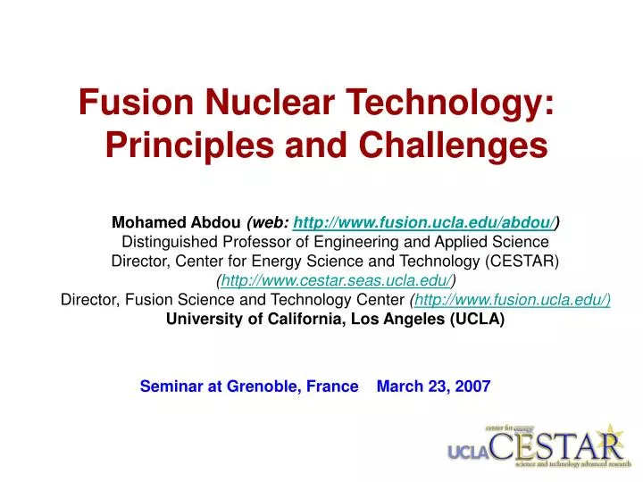
Fusion Nuclear Technology: Principles and Challenges. Mohamed Abdou (web: http://www.fusion.ucla.edu/abdou/ ) Distinguished Professor of Engineering and Applied Science Director, Center for Energy Science and Technology (CESTAR) ( http://www.cestar.seas.ucla.edu/ )

E N D
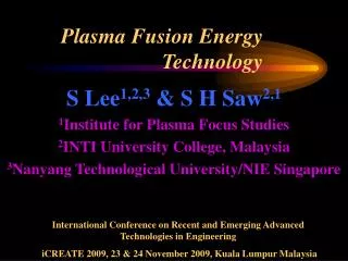
Fusion Nuclear Technology: Principles and Challenges Mohamed Abdou (web: http://www.fusion.ucla.edu/abdou/) Distinguished Professor of Engineering and Applied Science Director, Center for Energy Science and Technology (CESTAR) (http://www.cestar.seas.ucla.edu/) Director, Fusion Science and Technology Center (http://www.fusion.ucla.edu/) University of California, Los Angeles (UCLA) Seminar at Grenoble, France March 23, 2007
Incentives for Developing Fusion • Fusion powers the Sun and the stars • It is now within reach for use on Earth • In the fusion process lighter elements are “fused” together, making heavier elements and producing prodigious amounts of energy • Fusion offers very attractive features: • Sustainable energy source (for DT cycle; provided that Breeding Blankets are successfully developed) • No emission of Greenhouse or other polluting gases • No risk of a severe accident • No long-lived radioactive waste • Fusion energy can be used to produce electricity and hydrogen, and for desalination
ITER • The World is about to construct the next step in fusion development, a device called ITER • ITER will demonstrate the scientific and technological feasibility of fusion energy for peaceful purposes • ITER will produce 500 MW of fusion power • Cost, including R&D, is 15 billion dollars
ITER Design - Main Features Divertor Central Solenoid Blanket Module Vacuum Vessel Outer Intercoil Structure Cryostat Toroidal Field Coil Port Plug (IC Heating) Poloidal Field Coil Machine Gravity Supports Torus Cryopump
ITER is a collaborative effort among Europe, Japan, US, Russia, China and South Korea
Fusion Nuclear Technology (FNT) Fusion Power & Fuel Cycle Technology FNT Components from the edge of the Plasma to TF Coils(Reactor “Core”) 1. Blanket Components 2. Plasma Interactive and High Heat Flux Components a. divertor, limiter b. rf antennas, launchers, wave guides, etc. 3. Vacuum Vessel & Shield Components Other Components affected by the Nuclear Environment 4. Tritium Processing Systems 5. Instrumentation and Control Systems 6. Remote Maintenance Components 7. Heat Transport and Power Conversion Systems
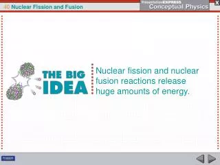
The Deuterium-Tritium (D-T) Cycle • World Program is focused on the D-T cycle (easiest to ignite): D + T → n + α+ 17.58 MeV • The fusion energy (17.58 MeV per reaction) appears as Kinetic Energy of neutrons (14.06 MeV) and alphas (3.52 MeV) • Tritium does not exist in nature! Decay half-life is 12.3 years (Tritium must be generated inside the fusion system to have a sustainable fuel cycle) • The only possibility to adequately breed tritium is through neutron interactions with lithium • Lithium, in some form, must be used in the fusion system
Natural lithium contains 7.42% 6Li and 92.58% 7Li. The 7Li(n;n’a)t reaction is a threshold reaction and requires an incident neutron energy in excess of 2.8 MeV. Tritium Breeding 6Li (n,a) t 7Li (n;n’a) t
Blanket (including first wall) Blanket Functions: • Power Extraction • Convert kinetic energy of neutrons and secondary gamma rays into heat • Absorb plasma radiation on the first wall • Extract the heat (at high temperature, for energy conversion) • Tritium Breeding • Tritium breeding, extraction, and control • Must have lithium in some form for tritium breeding • Physical Boundary for the Plasma • Physical boundary surrounding the plasma, inside the vacuum vessel • Provide access for plasma heating, fueling • Must be compatible with plasma operation • Innovative blanket concepts can improve plasma stability and confinement • Radiation Shielding of the Vacuum Vessel
Blanket Concepts(many concepts proposed worldwide) • Solid Breeder Concepts • Always separately cooled • Solid Breeder: Lithium Ceramic (Li2O, Li4SiO4, Li2TiO3, Li2ZrO3) • Coolant: Helium or Water • Liquid Breeder Concepts Liquid breeder can be: a) Liquid metal (high conductivity, low Pr): Li, or 83Pb 17Li b) Molten salt (low conductivity, high Pr): Flibe (LiF)n· (BeF2), Flinabe (LiF-BeF2-NaF) B.1. Self-Cooled • Liquid breeder is circulated at high enough speed to also serve as coolant B.2. Separately Cooled • A separate coolant is used (e.g., helium) • The breeder is circulated only at low speed for tritium extraction B.3. Dual Coolant • FW and structure are cooled with separate coolant (He) • Breeding zone is self-cooled
A Helium-Cooled Li-Ceramic Breeder Concept: Example • Material Functions • Beryllium (pebble bed) for neutron multiplication • Ceramic breeder (Li4SiO4, Li2TiO3, Li2O, etc.) for tritium breeding • Helium purge (low pressure) to remove tritium through the “interconnected porosity” in ceramic breeder • High pressure Helium cooling in structure (ferritic steel) Several configurations exist (e.g. wall parallel or “head on” breeder/Be arrangements)
Examples of solid breeder blankets that utilize immobile solid lithium ceramic breeder and Be multiplier for tritium self-sufficiency EU HCPB DEMO Module JA HCSB Module Tritium Breeder Li2TiO3, Li2O (<2mm) Neutron Multiplier Be, Be12Ti (<2mm) First Wall (RAFS, F82H) phase IARIES-CS HCCB Breeder Unit to be inserted into the space between the grid plates ODS +FS
Solid Breeder Blanket Issues • Tritium self-sufficiency • Breeder/Multiplier/structure interactive effects under nuclear heating and irradiation • Tritium inventory, recovery and control; development of tritium permeation barriers • Effective thermal conductivity, interface thermal conductance, thermal control • Allowable operating temperature window for breeder • Failure modes, effects, and rates • Mass transfer • Temperature limits for structural materials and coolants • Mechanical loads caused by major plasma disruption • Response to off-normal conditions
Liquid Breeders • Many liquid breeder concepts exist, all of which have key feasibility issues. Selection can not prudently be made before additional R&D results become available. • Type of Liquid Breeder: Two different classes of materials with markedly different issues. • Liquid Metal: Li, 83Pb 17Li High conductivity, low Pr number Dominant issues: MHD, chemical reactivity for Li, tritium permeation for LiPb • Molten Salt: Flibe (LiF)n· (BeF2), Flinabe (LiF-BeF2-NaF) Low conductivity, high Pr number Dominant Issues: Melting point, chemistry, tritium control
Liquid Breeder Blanket Concepts • Self-Cooled • Liquid breeder circulated at high speed to serve as coolant • Concepts: Li/V, Flibe/advanced ferritic, flinabe/FS • Separately Cooled • A separate coolant, typically helium, is used. The breeder is circulated at low speed for tritium extraction. • Concepts: LiPb/He/FS, Li/He/FS • Dual Coolant • First Wall (highest heat flux region) and structure are cooled with a separate coolant (helium). The idea is to keep the temperature of the structure (ferritic steel) below 550ºC, and the interface temperature below 480ºC. • The liquid breeder is self-cooled; i.e., in the breeder region, the liquid serves as breeder and coolant. The temperature of the breeder can be kept higher than the structure temperature through design, leading to higher thermal efficiency.
Module box(container & surface heat flux extraction) Breeder cooling unit (heat extraction from PbLi) [0.5-1.5] mm/s [18-54] mm/s Stiffening structure (resistance to accidental in-box pressurization i.e He leakage) He collector system (back) HCLL PbLi flow scheme EU – The Helium-Cooled Lead Lithium (HCLL) DEMO Blanket Concept
Vanadium structure Lithium Li Secondary Shield Li Primary Shield Li Breeding Zone (Li flow) Reflector Primary shield (Tenelon) Secondary shield (B4C) Reflector Vanadium structure Lithium Li/Vanadium Blanket Concept
DCLL Typical Unit Cell Self-cooled Pb-17Li Breeding Zone SiC FCI He-cooled steelstructure Pathway Toward Higher Temperature Through Innovative Designs with Current Structural Material (Ferritic Steel):Dual Coolant Lead-Lithium (DCLL) FW/Blanket Concept • First wall and ferritic steel structure cooled with helium • Breeding zone is self-cooled • Structure and Breeding zone are separated by SiCf/SiC composite flow channel inserts (FCIs) that • Provide thermal insulation to decouple PbLi bulk flow temperature from ferritic steel wall • Provide electrical insulation to reduce MHD pressure drop in the flowing breeding zone Pb-17Li exit temperature can be significantly higher than the operating temperature of the steel structure High Efficiency
Flows of electrically conducting coolants will experience complicated magnetohydrodynamic (MHD) effects What is magnetohydrodynamics (MHD)? • Motion of a conductor in a magnetic field produces an EMF that can induce current in the liquid. This must be added to Ohm’s law: • Any induced current in the liquid results in an additional body force in the liquid that usually opposes the motion. This body force must be included in the Navier-Stokes equation of motion: • For liquid metal coolant, this body force can have dramatic impact on the flow: e.g. enormous MHD drag, highly distorted velocity profiles, non-uniform flow distribution, modified or suppressed turbulent fluctuations
Main Issue for Flowing Liquid Metal in Blankets: MHD Pressure Drop Feasibility issue – Lorentz force resulting from LM motion across the magnetic field generates MHD retarding force that is very high for electrically conducting ducts and complex geometry flow elements Thin wall MHD pressure drop formula p, pressureL, flow lengthJ, current densityB, magnetic inductionV, velocity, conductivity (LM or wall)a,t, duct size, wall thickness
Inboard is the critical limiting region for LM blankets • B is very high! 10-12T • L is fixed to reactor height by poor access • a is fixed by allowable shielding size • Tmax is fixed by material limits Combining Power balance formula L With Pipe wall stress formula With thin wall MHD pressure drop formula (previous slide) gives: (Sze, 1992) Pipe stress is INDEPENDENT of wall thickness to first order and highly constrained by reactor size and power!
No pipe stress window for inboard blanket operation for Self-Cooled LM blankets (e.g. bare wall Li/V) (even with aggressive assumptions) U ~ 0.16 m/s Pmax ~ 5-10 MPa • Pipe stress >200 MPa will result just to remove nuclear heat • Higher stress values will result when one considers the real effects of: • 3D features like flow distribution and collection manifolds • First wall cooling likely requiring V ~ 1 m/s Unacceptable Marginal Allowable ARIES-RS ITER Best Possible DEMO Base Case for bare wall Li/V: NWL = 2.5 MW/m2 L = 8 m, a = 20 cm T = 300K
Net JxB body force p = cVB2 where c = (tw w)/(a ) For high magnetic field and high speed (self-cooled LM concepts in inboard region) the pressure drop is large The resulting stresses on the wall exceed the allowable stress for candidate structural materials Perfect insulators make the net MHD body force zero But insulator coating crack tolerance is very low (~10-7). It appears impossible to develop practical insulators under fusion environment conditions with large temperature, stress, and radiation gradients Self-healing coatings have been proposed but none has yet been found (research is on-going) Large MHD drag results in large MHD pressure drop Conducting walls Insulated walls Lines of current enter the low resistance wall – leads to very high induced current and high pressure drop All current must close in the liquid near the wall – net drag from jxB force is zero
Issues with the Lithium/Vanadium Concept • Li/V was the U.S. choice for a long time, because of its perceived simplicity. But negative R&D results and lack of progress on serious feasibility issues have eliminated U.S. interest in this concept as a near-term option. Issues • Insulator • Insulator coating is required • Crack tolerance (10-7) appears too low to be achievable in the fusion environment • “Self-healing” coatings can solve the problem, but none has yet been found (research is ongoing) • Corrosion at high temperature (coupled to coating development) • Existing compatibility data are limited to maximum temperature of 550ºC and do not support the BCSS reported corrosion limit of 5mm/year at 650ºC • Tritium recovery and control Insulating layer Conducting walls Leakage current Electric currents lines Crack • Vanadium alloy development is very costly and requires a very long time to complete
Proposed US DCLL TBM Cutaway US DCLL TBM – Cutaway Views PbLi Flow Channels PbLi SiC FCI He-cooled First Wall He 484 mm 2 mm gap He
Flow Channel Inserts are a critical element of the high outlet temperature DCLL • FCIs are roughly box channel shapes made from some material with low electrical and thermal conductivity • SiC/SiC composites and SiC foams are primary candidate materials • They will slip inside the He Cooled RAFS structure, but not be rigidly attached • They will slip fit over each other, but not be rigidly attached or sealed • FCIs may have a thin slot or holes in one wall to allow better pressure equalization between the PbLi in the main flow and in the gap region • FCIs in front channels, back channels, and access pipes will be subjected to different thermal and pressure conditions; and will likely have different designs and thermal and electrical property optimization
Example: Interaction between MHD flow and FCI behavior are highly coupled and require fusion environment • PbLi flow is strongly influenced by MHD interaction with plasma confinement field and buoyancy-driven convection driven by spatially non-uniform volumetric nuclear heating • Temperature and thermal stress of SiC FCI are determined by this MHD flow and convective heat transport processes • Deformation and cracking of the FCI depend on FCI temperature and thermal stress coupled with early-life radiation damage effects in ceramics • Cracking and movement of the FCIs will strongly influence MHD flow behavior by opening up new conduction paths that change electric current profiles Simulation of 2D MHD turbulence in PbLi flow FCI temperature, stress and deformation Similarly, coupled phenomena in tritium permeation, corrosion, ceramic breeder thermomechanics, and many other blanket and material behaviors
Key DCLL parameters in three blanket scenarios *Velocity, dimensions, and dimensionless parameters are for the poloidal flow. DEMO parameters are for the outboard blanket. Abdou Lecture 4
Parametric analysis was performed for poloidal flows to access FCI effectiveness as electric/thermal insulator SiC=1-500 S/m, kSiC=2-20 W/m-K Strong effect of SiC on the temperature field exists via changes in the velocity profile FCI properties were preliminary identified: SiC~100 S/m, kSiC~2 W/m-K Temperature Profile for Model DEMO Case kFCI = 2 W/m-K FCI Pb-Li FS GAP sFCI = 5 S/m 20 S/m 100 S/m MHD / Heat Transfer analysis (DEMO)
Molten Salt Blanket Concepts • Lithium-containing molten salts are used as the coolant for the Molten Salt Reactor Experiment (MSRE) • Examples of molten salt are: • Flibe: (LiF)n· (BeF2) • Flinabe: (LiF-BeF2-NaF) • The melting point for flibe is high (460ºC for n = 2, 380ºC for n = 1) • Flinabe has a lower melting point (recent measurement at SNL gives about 300ºC) • Flibe has low electrical conductivity, low thermal conductivity
Molten Salt Concepts: Advantages and Issues Advantages • Very low pressure operation • Very low tritium solubility • Low MHD interaction • Relatively inert with air and water • Pure material compatible with many structural materials • Relatively low thermal conductivity allows dual coolant concept (high thermal efficiency) without the use of flow-channel inserts Disadvantages • High melting temperature • Need additional Be for tritium breeding • Transmutation products may cause high corrosion • Low tritium solubility means high tritium partial pressure (tritium control problem) • Limited heat removal capability, unless operating at high Re (not an issue for dual-coolant concepts)
Summary of MHD issues of liquid blankets Abdou Lecture 4
Issues and R&D on Liquid Metal Breeder Blankets • Fabrication techniques for SiC Inserts • MHD and thermalhydraulic experiments on SiC flow channel inserts with Pb-Li alloy • Pb-Li and Helium loop technology and out-of-pile test facilities • MHD-Computational Fluid Dynamics simulation • Tritium permeation barriers • Corrosion experiments • Test modules design, fabrication with RAFS, preliminary testing • Instrumentation for nuclear environment
Fusion environment is unique and complex:multi-component fields with gradients • Particle Flux(energy and density, gradients) • Magnetic Field (3-component with gradients) • Steady Field • Time-Varying Field • Mechanical Forces • Normal/Off-Normal • Thermal/Chemical/Mechanical/ Electrical/Magnetic Interactions • Neutrons (fluence, spectrum, temporal and spatial gradients) • Radiation Effects (at relevant temperatures, stresses, loading conditions) • Bulk Heating • Tritium Production • Activation • Heat Sources (magnitude, gradient) • Bulk (from neutrons and gammas) • Surface • Synergistic Effects • Combined environmental loading conditions • Interactions among physical elements of components Multi-function blanket in multi-component field environmentleads to: • Multi-Physics, Multi-Scale PhenomenaRich Science to Study - Synergistic effectsthatcannotbe anticipated from simulations & separate effects tests. Even some key separate effects in the blanket can not be produced in non-fusion facilities (e.g. volumetric heating with gradients) A true fusion environment is ESSENTIAL to Activate mechanisms that cause prototypical coupled phenomena and integrated behavior
He pipes to TCWS TBM System (TBM + T-Extrac, Heat Transport/Exchange…) Bio-shield A PbLi loop Transporter located in the Port Cell Area 2.2 m Equatorial Port Plug Assy. Vacuum Vessel Port Frame TBM Assy ITER Provides Substantial Hardware Capabilities for Testing of Blanket System • ITER has allocated 3 ITER equatorial ports (1.75 x 2.2 m2) for TBM testing • Each port can accommodate only 2 Modules (i.e. 6 TBMs max) • But, 12 modules are proposed by the parties • Aggressive competition for Space
Challenging Fusion Nuclear Technology Issues • Tritium Supply & Tritium Self-Sufficiency • High Power Density • High Temperature • MHD for Liquid Breeders / Coolants • Tritium Control (Permeation) • Reliability / Maintainability / Availability • Testing in Fusion Facilities
Tritium Self-Sufficiency • TBR ≡ Tritium Breeding Ratio = = Rate of tritium production (primarily in the blanket) = Rate of tritium consumption (burnt in plasma) Tritium self-sufficiency condition: Λa > Λr Λr = Required tritium breeding ratio Λr is 1 + G, where G is the margin required to: a) compensate for losses and radioactive decay between production and use, b) supply inventory for start-up of other fusion systems, and c) provide a hold-up inventory, which accounts for the time delay between production and use as well as reserve storage. Λris dependent on many system parameters and features such as plasma edge recycling, tritium fractional burn up in the plasma, tritium inventories, doubling time, efficiency/capacity/reliability of the tritium processing system, etc. Λa = Achievable breeding ratio Λa is a function of FW thickness, amount of structure in the blanket, presence of stabilizing shell materials, PFC coating/tile/materials, material and geometry for divertor, plasma heating, fueling and penetration.
Current physics and technology concepts lead to a “narrow window” for attaining Tritium self-sufficiency Fusion power 1.5GW Reserve time 2 days Waste removal efficiency 0.9 (See paper for details) td = doubling time Required TBR td=1 yr Max achievable TBR ≤ 1.15 td=5 yr td=10 yr “Window” for Tritium self sufficiency Fractional burn-up [%]
Fueling Fuel management Fuel inline storage Tritium shipment/permanent storage Plasma exhaust processing Impurity separation Plasma Isotope separation system FW coolant processing Impurity processing Plasma FacingComponent Coolant tritium recovery system Tritium waste treatment (TWT) PFC Coolant Water stream and air processing Solid waste Blanket Coolant processing waste Breeder Blanket Blanket tritium recovery system Only for solid breeder or liquid breeder design using separate coolant Only for liquid breeder as coolant design Fuel Cycle Dynamics The D-T fuel cycle includes many components whose operation parameters and their uncertainties impact the required TBR • Examples of key parameters: • ß: Tritium fraction burn-up • Ti: mean T residence time in each component • Tritium inventory in each component • Doubling time • Days of tritium reserves • Extraction inefficiency in plasma exhaust processing
Structural Materials • Key issues include thermal stress capacity, coolant compatibility, waste disposal, and radiation damage effects • The 3 leading candidates are ferritic/martensitic steel, V alloys and SiC/SiC (based on safety, waste disposal, and performance considerations) • The ferritic/martensitic steel is the reference structural material for DEMO (Commercial alloys (Ti alloys, Ni base superalloys, refractory alloys, etc.) have been shown to be unacceptable for fusion for various technical reasons)
Fission (PWR) Fusion structure Coal Tritium in fusion
Lessons learned:The most challenging problems in FNT are at theINTERFACES • Examples: • MHD insulators • Thermal insulators • Corrosion(liquid/structure interface temperature limit) • Tritium permeation • Research on these interfaces must be done jointly by blanket and materials researchers
Need for High Power Density Capability • To improve potential attractiveness of fusion power compared to other energy sources (e.g., fission) • Some plasma confinement schemes have the potential to produce burning plasmas with high power density • FW/Blanket/Divertor concepts developed in the 1970s and ’80s have limitations on power density capability (wall load and surface heat flux) • Substantial PROGRESS has been made in this area over the past several years (e.g. in the APEX Study in the US )
( 1 / failure rate ) + 1 / failure rate replacement time Reliability/Maintainability/Availabilityis one of theremaining “Grand Challenges”to Fusion Energy Development. Chamber Technology R&D is necessary to meet this Grand Challenge. Need High Power Density/Physics-Technology Partnership • High-Performance Plasma Need Low -Chamber Technology Capabilities Failure Rate × + + replacement cost C i O & M = COE × × × h P Availability M fusion th Energy Need High Temp. Multiplication Energy Extraction Need High Availability / Simpler Technological and Material Constraints · Need Low Failure Rate: - Innovative Chamber Technology · Need Short Maintenance Time: - Simple Configuration Confinement - Easier to Maintain Chamber Technology
Availability = MTBFMTBF + MTTR Current plasma confinement schemes and configurations have: • Relatively long MTTR (weeks to months) • Required MTBF must be high • Large first wall area • Unit failure rate must be very lowMTBF ~ 1/(area • unit failure rate) Reliability requirements are more demandingthan for other non-fusion technologies
The reliability requirements on the Blanket/FW (in current confinement concepts that have long MTTR > 1 week) are most challenging and pose critical concerns. These must be seriously addressed as an integral part of the R&D pathway to DEMO. Impact on ITER is predicted to be serious. It is a DRIVER for CTF.