Download
1 / 18
180 likes | 193 Views
FVTX Mechanical Status :. Walter Sondheim - LANL Mechanical Project Engineer; VTX & FVTX. VTX-FVTX Half Assembly for Introduction:. “Big Wheel” region, read-out electronics for VTX and FVTX; 5 layers – 1 stripixel, 3 pixel and 1 FVTX, (from the IP out)

E N D
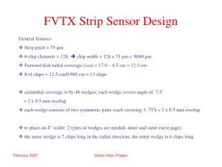
FVTX Mechanical Status: Walter Sondheim - LANL Mechanical Project Engineer;VTX & FVTX FVTX Review, November 16th, 2009
VTX-FVTX Half Assembly for Introduction: “Big Wheel” region, read-out electronics for VTX and FVTX; 5 layers – 1 stripixel, 3 pixel and 1 FVTX, (from the IP out) One of two FVTX detector assemblies per half VTX assembly Half VTX assembly; 4 layers - inner 2 pixel sensors, outer 2 are “stripixel” sensors. Support structure with isolation mounts for space frame and rigid mounting for ancillary system. Mounting is off support beams that run between CM poles. FVTX Review, November 16th, 2009
FVTX Half Assembly for Introduction: 1 Big Wheel per FVTX assembly, 6 ROCs, 8 wedges per ROC card. 4 detector stations per FVTX assembly, each off-set in phi. Each station has its own cooling circuit, as well as one around the Big Wheel. Each station has “wedge” silicon mini-strip detectors mounted to both sides, 4 layers per station disk. Beryllium beam pipe 41.021 mm OD X 800.0 mm long. FVTX Review, November 16th, 2009
Wedge Sensor Module; stations 2 & 3 Upstream module, upper level: FPHX read-out-chips, 13 on each side of sensor, 128 channels each, 300. – 528. microwatts per channel, 1.0 – 1.76 watts/wedge. Silicon sensor, 320. microns. HDI, 334. microns. Each wedge assembly is mounted to a station disk by 2 #2 screws and 2 locating pins. Carbon back-plane, 1.56 mm, K13C2U. Fab at LBNL composite shop. Spacers – POCO graphite, AXM5Q, 2 versions of each. Separate ground connection point for Carbon. Hirose DF18 series connector and Hirose H.FL series mini-coax for bias. FVTX Review, November 16th, 2009
Wedge Sensor Module assembly: 15 Chip large wedge prototype sensor module shown. • Chips mounted to HDI using Arclad 7876 transfer tape. • Sensor mounted to HDI using strips of Arclad 7876 and Tra-bond 2902 silver conductive epoxy. • HDI mounted to Carbon support wedge using Arclad 7876. • Graphite spacers mounted to Carbon support Arclad 7876. • Wedge assembly mounted to station disk thermal grease. • Each large wedge produces 1.33 watts at 400 microwatts/channel. FVTX Review, November 16th, 2009
Wedge Sensor Module assembly: Stations 2 & 3, two different HDI bends and two different spacers Station 1, two different HDI bends and two different spacers Station 4, four different HDI bends and two different spacers FVTX Review, November 16th, 2009
Station sub-assembly, stations 2, 3 or 4: Each wedge staggered in Z, 15 degrees between wedges on one side, upstream to downstream sides of panel offset by 7.5 degrees – hermetic in phi. Each silicon sensor covers 7.5 degrees in phi. Thermal load - 32 watts @ 400 microwatts/channel. Thermally conductive blocks to transfer heat from wedge to support panel POCO Graphite AXM5Q. Outer block is just above cooling channel in disk. Four layers of 15 degree wedges, 2 layers on each side of support panel, front to back wedges rotated by 3.75 degrees. M55J Carbon faced support panel PEEK mounting #2 screw – (phillips head) Mounting and alignment pins in tabs, 3 per station half disk. FVTX Review, November 16th, 2009
Station Support Panel Construction: M55J face sheet, .25 mm Wedge locating pin Coolant channel, PEEK 3 Holes for survey flag along edge Hose barb PEEK Threaded insert for handle Core – Allcomp Inc. Carbon foam, 4.76 mm Mounting tab M55J face sheet, .25 mm Core insert PEEK, pins SS, screws PEEK FVTX Review, November 16th, 2009
FVTX station half panel status: • Preliminary drawings for all four stations have been completed. • Even with the “staggered” orientation of the stations, there are only two distinct panels – one for station 1 and the second for stations 2,3 & 4. The stagger, or phi rotation, is built into the FVTX cage. • No additional analysis for the station disk has been performed since early 2008. The need for an analysis of a station disk laying flat is being evaluated.. • The cooling loop around the outer perimeter of the disk is of an enclosed cavity design – solid PEEK material with Carbon face sheets bonded to it as the other two sides for the channel. • Alignment flag placements have been included at three locations around the outer perimeter of the station half disk. Targets from Hubbs Machine, Cedar Hill, Missouri, will be used. Walter Sondheim, UNM, July 16th, 2009
FVTX “Staggered” Cage: Cage design uses CN60 carbon fabric with a EX1515 resin. FEA analysis indicates very rigid structure < 25. microns. Blocks and flanges POCO graphite AXM5Q. Note: the mounting blocks for the 4 stations will be clocked in 1 degree increments. Each FVTX interfaces directly with the VTX space-frame. For scale: 400. mm in diameter, 187. mm in length. Penetrations in shell for survey/alignment flags. Fabrication will take place at LBNLcomposite shop. Mounting points to VTX space frame beams. FVTX Review, November 16th, 2009
FVTX Cage – staggered station positions: Station 1 0 degree.Station 2 2.8125 degrees.Station 3 .9375 degrees.Station 4 1.8750 degrees. Mating half cage is the same, rotates about the beam axis 180 degrees. Walter Sondheim, UNM, July 16th, 2009
Half Cage Assembly with Liquid Cooling Circuit: Outlets:6.16 °C,@19.5psi if parallel circuits. Outlets:7.73ºC,@18.22psi if circuits in series Novec 7200: Boiling point 76 degree C Melting point -138 degree C Vapor pressure 109 mmHg @ 25 degrees C Neutron irradiation study at LANL’s WNR facility – total dose 6.7 X 10**11 n/cm**2, nominal energy 800 Mev. Samples were sent to 3M for analysis of free Fluoride, no indication of significant degradation. Each station can be cooled in parallel or series with the other stations. Pressure drop per stations 2,3&4-.5psi, staion1-.28psi Delta-T per ½ station 1.8 degrees C, delta p .4 psi Coolant 3M Novec 7200 Thermal load – 108.3 watts half cage @ 400 microwatts/channel Inlet flow rate per station 28.2 ml/sec Inlets: 5.5°C,@ 20.psi FVTX Review, November 16th, 2009
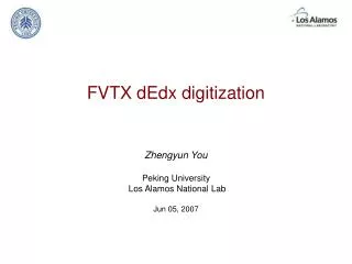
Coolant to FPHX Chips Thermal Path: Approximate temperatures with 5.5°C coolant flowing at Re~14,700 FVTX Review, November 16th, 2009
Coolant to FPHX Chips Thermal Path: Thermal measurements made on 15 chip wedge assembly, powered LVDS at 390. ma, 2.6 V = 528.1 microwatts per channel. Measured 29 ° C to 36 ° C along 13 chips, no coolant or contact with Aluminum plate. Temperature dropped 2 ° C when spacers in contact with Aluminum @ 23 ° C. Sensor deflection and temperature differential across the wedge vary linearly with chip power. FVTX Review, November 16th, 2009
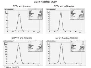
Temperature distribution along large wedge: Constraint temperature was varied to keep peak chip temperature at 21°C 23° 16.5° 12° 200 µW/Channel Base Temperature 17.36° C 300 µW/Channel Base Temperature 15.54° C 410 µW/Channel Base Temperature 13.53° C 500 µW/Channel Base Temperature 11.89° C FVTX Review, November 16th, 2009
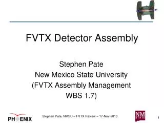
Total Wedge Deflection: +0.0002 m 0.0 -0.0002 m 200 µW/Channel 300 µW/Channel 410 µW/Channel 500 µW/Channel FVTX Review, November 16th, 2009
Two Independent Halves: “Big Wheel” cooling plate with coolant channel along perimeter, 3. mm Aluminum. ROC cards, 38. watts/card – 228 watts per Aluminum disk. Wedge readout extension cables, 16 variation – each modeled. Gas seal between layers, Silicone. Work will begin shortly on design for assembly jigs for disks and aids for mounting disks and cables into cage. An external support structure for the cage is needed for final assembly and testing, prior to mounting into the ends of the VTX space frame. This half FVTX assembly is stand alone, can be tested independently of the rest of the detector in a lab, with coolant and a support stand. FVTX Review, November 16th, 2009
Summary: WBS 1.6 Mechanics – Schedule Dates & Manpower • WBS 1.6 • WBS 1.6.1 Specifications 10/21/2005 – 2/9/2006 • WBS 1.6.2 Support Structure Cage 4/1/2007 – 7/9/2009 • WBS 1.6.3 Wedge Backplane 4/11/2008 – 10/15/2009 • WBS 1.6.4 Support Disk 1/4/2007 – 12/1/2009 • WBS 1.6.5 Alignment and Assembly 8/1/2008 – 2/15/2010 • Milestones • Final design drawings for wedge components complete • Carbon backing • HDI • Spacers • Thermal and mechanical analysis complete • Final design drawings for the FVTX cage complete • Final design drawings for station disk complete in December FVTX Review, November 16th, 2009