Download
1 / 28
280 likes | 424 Views
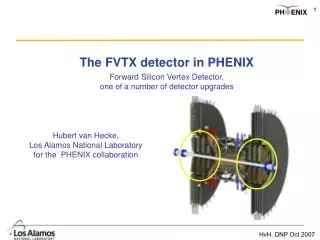
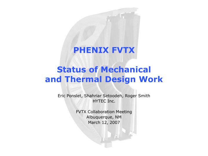
PHENIX FVTX Status of Mechanical and Thermal Design Work. Eric Ponslet, Shahriar Setoodeh, Roger Smith HYTEC Inc. FVTX Collaboration Meeting Albuquerque, NM March 12, 2007. Latest Baseline Design. Still Evolving… Modular Design

E N D
PHENIX FVTXStatus of Mechanical and Thermal Design Work Eric Ponslet, Shahriar Setoodeh, Roger Smith HYTEC Inc. FVTX Collaboration Meeting Albuquerque, NM March 12, 2007
Latest Baseline Design • Still Evolving… • Modular Design • Detector module (“wedge”) Half disk Half Cage (“clamshell”) FVTX • Wedge is Built on a Graphite Fiber/Cyanate Ester Thermal Backplane • Serves as structural support and heat transfer path to edge cooling • 0.76mm thick K13CU/CyE • Very high stiffness and thermal conductivity fiber • Symmetric, balanced layup (won’t warp from temperature changes) • Wedges are Fastened to Support Panel • Two alignment pins (ceramic?) and 3 screws (nylon) per wedge • Thick RT-cured silicone bridge provides thermal interface to cooled support panel • Allows replacement of single defective wedge • BUT: requires cutting the Silicone thermal bridge • Half-Disk Support Panel and Support Cage • Sandwich construction: Graphite fiber (M55J) faces and aluminum honeycomb • Liquid Cooling • Tube embedded in panel in place of core, near OD of half disk • Single phase coolant at high flow rate (turbulent)
Backplane HDI Detector ROC’s Rigid, thermally conductive epoxy Rigid epoxy Wedge Design Connectors for extension cables Screw (nylon) HDI Pin hole (for alignment) Detector ROC’s (26) Backplane (0.76mm graphite fiber composite) All bonded with rigid epoxies Screw (nylon) Pin hole (for alignment)
Half-Disk Assembly ROC Detector Support Tab HDI Screw Pin Support Tab Support Panel Silicone bond (for heat transfer) Support Tab
Cooling and Tab Detail Silicon detectors, HDIs, and back-planes made transparent for clarity Screw hole (mounting to cage) Hose barb for coolant Pin hole (mounting to cage) Built-in cooling tube Screw (holds wedge on disk) Pin (aligns wedge on disk) Silicone heat transfer bridge (RT-cured, 2-part silicone) ROC Silicon detector
Half-Disk Assembly: Details Single piece plastic insert for screws and pins Standoff plate Thermally conductive Silicone Foam core Honeycomb core Plastic inserts for screws and pins
Support Panel Construction GFRP Face sheet (0.25mm) Insert for pin (TBD plastic) Locating pin Standoff plate (TBD Plastic) Insert for screw (TBD plastic) Cooling tube Hose barb Foam core (TBD mat’l) Core insert for pins and screws (TBD plastic) Honeycomb core (4.76mm, 32 kg/m3) GFRP Face sheet (0.25mm) Mounting tab
Half Cage Assembly Cooling hose (silicone) Y Z Station 1 Station 2 Station 3 Station 4
FVTX Assembly VTX Pixel barrel (#4) VTX Pixel barrel (#3) VTX Pixel barrel (#2) VTX Pixel barrel (#1) 57mm 54.5mm 54.5mm Too close! (move FVTX station 1 back?) FVTX Station 1 FVTX Station 2 FVTX Station 4 FVTX Station 3
Modularity & Testability • Three Levels of Subassemblies • Can all be tested independently • Test stands will be designed • Single Wedge stand will need to incorporate cooling feature Detector Module (aka Wedge) Half Disk Module Half Cage Module
Summary of Key Requirements • Environment • Operate in dry Nitrogen at atmospheric pressure and RT • Radiation dose: <200 kRad over 10 years (very low) • 10 year design life • Functional • Detector modules must be individually removable during initial integration • FVTX must be assembled around beam line (“clamshell design”) • Heat Dissipation • 100μW/channel, 128 channels/ROC • 26 ROC’s/detector (stations 2, 3, 4) • 10(?) ROC’s/detector (station 1) • Temperature Limits (ROC and detector) • Not specified • Radiation Length Limit of Station • Not specified • Dimensional Accuracy/Stability • See next slide
Dimensional Accuracy Requirements • Initial Alignment or Surveying Tolerance • Detector relative to station • Initial assembly/surveying of half-disks X,Y < ±10μm Z < ±200μm (75μm goal) • Station location • Initial assembly/surveying of half cages and complete system X,Y,Z < ±200μm • Static Deformations • Non-rigid-body deformations such as temperature-induced bowing of detectors X,Y < ±10μm Z < ±14μm • Stability • Unsteady Deformations and displacements (vibrations,…) X,Y < ±10μm Z < ±14μm
Radiation Length Status (1/2) • Total RL of Station 2, 3, or 4 • Area averaged to active area (45mm IR, 170mm OR) = 2.2% • Worst case local value = 4.3% (going through cooling tube) See notes on next slide
Radiation Length Status (2/2) • Notes: • Assumes 35cm RL (X0/ρ) for coolant (no data) • Assumes 1.2cm RL (X0/ρ) for Nickel (no data) • Honeycomb core is treated as uniform mass distribution • Titanium fittings not included (outside of active area) • Screws not included (type TBD; likely nylon so small impact) • Alignment pins not included (material TBD; may be removable)
Cooling Assumptions • Keep FVTX (and VTX) near Room Temperature • Eliminates difficulties with cold gas enclosure • flow dry nitrogen at RT • Mitigates thermal stress and dimensional stability issues • Power Removed • 8W per half disk (stations #2, 3, 4) • Cooling Tube Embedded in 3/16” Support Panel • Square cross section (3/16” by 3/16”) with super-thin (<50μm) nickel wall • Coolant • 3M Novec HFE-7000 • Completely harmless to (even live) micro-electronics • Environmentally friendly • Dense (1.4 × water) • Flow Regime • Single phase • Strongly turbulent • Re ~ 10,000 • Flow velocity ~ 0.7 m/sec • Flow rate ~ 20 g/sec = 14 mL/sec = 0.86 L/min (per ½ cage) • Flow-induced vibrations?
Coolant to ROC Thermal Path • Use Simple Correlations to Evaluate • Pressure drops • Temperature drop from fluid to cooling tube Warmest ROC: 20.3°C backplane (K13CU) Back of wedge backplane: 15°C Nickel tube (TBC) Outside of F.S: 12.6°C Inside of F.S: 12.2°C Inner Radius Outer Radius Tube wall: 11.3°C Foam (TBC) Bulk coolant: 10°C HDI Thermally Conductive Epoxy Panel core (Al HC) Thermally Conductive Silicone Approximate temperatures with 10°C coolant flowing at Re~10,000 (0.76mm K13CU backplane, 50μm Nickel tube, 0.2 W/mK epoxy, 0.75 W/mK silicone)
Liquid Cooling Circuit • Run 4 Half-disks in Series Outlet plane 4: 10.3°C Outlet plane 4: 10.9°C ROC station 2: ~21.2°C ROC station 4: ~20.6°C Warmest ROC, station 1: ~21.4°C FVTX Outlet: 11.1°C, ~3 psig ROC station 3: ~20.9°C FVTX Inlet: 10°C, ~5 psig Outlet plane 4: 10.6°C
Bonds: Silicon detector to HDI: rigid, RT-cured epoxy ROC to HDI: rigid, RT-cured, thermally conductive (1.5W/mK) epoxy HDI to backplane: rigid, RT-cured epoxy HDI Multi-layer Kapton HN/Cu (2 ground planes, 2 signal planes) Total thickness 0.176mm Backplane QI [0°/60°/-60°]2S K13CU/CyE graphite fiber composite Total thickness: 0.762mm Power Dissipation 26 chips per wedge (stations 2, 3, 4) 0.0128W/chip Effective Backplane Thermal Conductivities Estimated, based on historical test data (conservative) Kx = Ky = 130 W/m.K (~5 times lower than encapsulated TPG) Kz=1 W/m.K Boundary Conditions Bolted connections at 3 points Silicone thermal bridge near OD 15°C at back side of backplane, near cooling tube Wedge Analysis: Assumptions
Wedge Analysis: Temperature Distribution • Warmest ROC is 5.3ºC Warmer than Back Edge of Backplane • 10.3ºC warmer than coolant Min Tº = 15ºC (Boundary condition at back side of backplane) Radial Temperature Variation Temperature (°C) Max Tº = 20.3ºC Warmest ROC 3-D Temperature Contour Radius (from beam CL, meters)
Distortion (meters) Radius (from beam CL, meters) Wedge Analysis: Stresses and Distortions • Assuming Assembly at RT • Max distortion of silicon detector = 10.4μm • Max normal stress in silicon = 0.5 MPa (<< 10MPa, conservative allowable) • Max shear stress in bonds = 0.8 MPa (< ~13MPa allowable) Max deflection = 10.4μm Z deflection VS Radius Zero deflection (boundary conditions)
Wedge Design: Conclusions • GFRP Backplane is • Conductive enough: 5.3°C from outer edge to ROC • Rigid enough: 340 Hz natural frequency • HDI is Conductive Enough without Thermal Vias • Recommend using Kapton MT (higher conductivity) • Distortions are Low • <11 μm with 10°C coolant (<14μm requirement) • Stresses in Bond and Detector are Comfortably Low • No need for compliant adhesives
Max deflection of detector ~8μm Disk-Level Modeling: Thermal distortion • FEM of half disk, fully populated with detector modules • Used for stiffness & Deflection calculations Distortion due to cooling Fundamental vibration mode: 164 Hz
1: bond HDI to Backplane 2: bond detector to HDI/Backplane Assembly of Detector Module • Assembly Concept Based on • Base tool • Vacuum chuck • Keep backplane flat • Holds backplane • Mechanically aligned (2 pins) • Bonding tools • Aligned to base with two pins • Vacuum chucks • Keep things flat • One to hold HDI • HDI optically aligned (or use pins) • Another to hold silicon detector • Detector optically aligned • Two-step assembly • Bond HDI to backplane • Bond detector to HDI/backplane assembly • Open Questions • Shim between tools to control bond thickness? • Continuous/discontinuous bonds?
Key Remaining Technical Issues • Requirements: • RL and ROC temperature requirements • Relate to science requirements and finalize • Design: • Gas enclosure • Concept & design • Signal processing boards • Dimensions • Support structure • Cooling • Cooling system • Refrigeration, pumping, and control system • Not currently within HYTEC’s scope • Design Verification • Prototypes and performance testing • Flow-induced vibrations • Cooling performance • Dimensional stability
Future Work: Before DOE Review • Finalize and Document Requirements (LANL) • RL • Temperature limits • Finish Preliminary Design (HYTEC, funded) • In progress, 3 more weeks • Document Preliminary Design (HYTEC, funded) • In progress, report expected by April 6
Future Work: Before Construction Phase • Not Funded, but Manpower is currently available • Detailed Design • Adhesive selection, inserts, station 1 • System Design • gas enclosure, “big wheel” • Cooling Hardware (not in HYTEC’s scope) • Internal: tubing, clamps, etc. • External/system: refrigeration, circulation, and control system • Prototyping • Detector module prototypes • GFRP backplanes + dummy HDI + dummy SSD (passive silicon wafer) + resistive heaters (ROC heat) • Used to • Test assembly tooling • Thermal cycling (stresses in bonds and SSD) • Heat transfer testing • Validate temperature induced deflections (TV Holography?) • Station prototype • One half disk (large) • Supported by dummy structure (no cage) • Populated with dummy detector modules • Used to • Test assembly and alignment concepts • Measure flow induced vibration (accelerometers)
Funding Issues • HYTEC has No Remaining FVTX Funds • Will finish preliminary design work and write report by April 6 • Funding Needed Before DOE Review • Continue refining design and updating CAD and analysis • Support DOE review (if needed) • Funding Needed Before Construction Phase • Complete and finalize design • Prototyping and testing Without new funding by early April, current engineering team will have to be re-assigned to other projects
Concluding Remarks • Structural/Thermal Design is Settling • Rigid • Stable • Modular • Numerous Details still TBD • Adhesives, joint details, tooling,… • Various System Issues still TBD • Gas enclosure, support and cooling of big wheel,… • One Technical Question • Flow induced vibrations? • Need disk prototype to evaluate • Need Bridge Funding through end of FY • Continuity of engineering support • Inevitable design changes to come • Remaining design tasks • Prototyping and performance testing