Download
1 / 19
190 likes | 273 Views
UML Use Case Diagramming Guidelines. What is UML?.

E N D
What is UML? • The Unified Modeling Language (UML) is a standard language for specifying, visualizing, constructing, and documenting the artifacts of software systems, as well as for business modeling and other non-software systems. The UML represents a collection of best engineering practices that have proven successful in the modeling of large and complex systems.1 The UML is a very important part of developing object oriented software and the software development process. The UML uses mostly graphical notations to express the design of software projects. Using the UML helps project teams communicate, explore potential designs, and validate the architectural design of the software.
Goals of UML • The primary goals in the design of the UML were: • Provide users with a ready-to-use, expressive visual modeling language so they can develop and exchange meaningful models. • Provide extensibility and specialization mechanisms to extend the core concepts. • Be independent of particular programming languages and development processes. • Provide a formal basis for understanding the modeling language. • Encourage the growth of the OO tools market. • Support higher-level development concepts such as collaborations, frameworks, patterns and components. • Integrate best practices.
Why Use UML? • As the strategic value of software increases for many companies, the industry looks for techniques to automate the production of software and to improve quality and reduce cost and time-to-market. These techniques include component technology, visual programming, patterns and frameworks. Businesses also seek techniques to manage the complexity of systems as they increase in scope and scale. In particular, they recognize the need to solve recurring architectural problems, such as physical distribution, concurrency, replication, security, load balancing and fault tolerance. Additionally, the development for the World Wide Web, while making some things simpler, has exacerbated these architectural problems. The Unified Modeling Language (UML) was designed to respond to these needs.
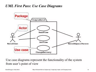
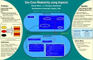
Use Case Diagramming • A use case diagram is “a diagram that shows the relationships among actors and use cases within a system.” Use case diagrams are often used to: • Provide an overview of all or part of the usage requirements for a system or organization in the form of an essential model or a business model • Communicate the scope of a development project • Model your analysis of your usage requirements in the form of a system use case model
Use Case Diagramming • A use case model is comprised of one or more use case diagrams and any supporting documentation such as use case specifications and actor definitions. • Within most use case models the use case specifications tend to be the primary artifact with use case diagrams filling a supporting role as the “glue” that keeps your requirements model together. • Use case models should be developed from the point of view of your project stakeholders and not from the (often technical) point of view of developers.
Use Case Diagramming • There are guidelines for: • Use Cases • Actors • Relationships • System Boundary Boxes
1- Use Cases • A use case describes a sequence of actions that provide a measurable value to an actor. A use case is drawn as a horizontal ellipse on a UML use case diagram, as you see in Figure 1. • Use Case Names Begin With a Strong Verb • Name Use Cases Using Domain Terminology • Place Your Primary Use Cases In The Top-Left Corner Of The Diagram • Imply Timing Considerations By Stacking Use Cases. As you see in Figure 1, the use cases that typically occur first are shown above those that appear later.
2. Actors • An actor is a person, organization, or external system that plays a role in one or more interactions with your system (actors are typically drawn as stick figures on UML Use Case diagrams). • Place Your Primary Actor(S) In The Top-Left Corner Of The Diagram • Draw Actors To The Outside Of A Use Case Diagram • Name Actors With Singular, Business-Relevant Nouns • Associate Each Actor With One Or More Use Cases • Actors Model Roles, Not Positions • Use <<system>> to Indicate System Actors • Actors Don’t Interact With One Another • Introduce an Actor Called “Time” to Initiate Scheduled Events
3. Relationships • There are several types of relationships that may appear on a use case diagram: • An association between an actor and a use case • An association between two use cases • A generalization between two actors • A generalization between two use cases
3. Relationships (cont.) • Indicate An Association Between An Actor And A Use Case If The Actor Appears Within The Use Case Logic • Avoid Arrowheads On Actor-Use Case Relationships • Apply <<include>> When You Know Exactly When To Invoke The Use Case • Apply <<extend>> When A Use Case May Be Invoked Across Several Use Case Steps • Introduce <<extend>> associations sparingly • Generalize Use Cases When a Single Condition Results In Significantly New Business Logic • Do Not Apply <<uses>>, <<includes>>, or <<extends>> • Avoid More Than Two Levels Of Use Case Associations • Place An Included Use Case To The Right Of The Invoking Use Case • Place An Extending Use Case Below The Parent Use Case • Apply the “Is Like” Rule to Use Case Generalization • Place an Inheriting Use Case Below The Base Use Case • Apply the “Is Like” Rule to Actor Inheritance • Place an Inheriting Actor Below the Parent Actor
4. System Boundary Boxes • The rectangle around the use cases is called the system boundary box and as the name suggests it indicates the scope of your system – the use cases inside the rectangle represent the functionality that you intend to implement. • Indicate Release Scope with a System Boundary Box. In Figure 2 you see that three system boundary boxes are included, each of which has a label indicating which release the various use cases have been assigned to. • Avoid Meaningless System Boundary Boxes.
Other Examples Array Stack Printer User Queue
Array Stack Set <<Uses> Inversing User <<Is a>> Queue Printer
Generate Daily report Returning item Customer Change item Operator
Generate Daily report uses Returning item uses Print uses extends Change item inherits Item stuck Customer inherits Receipt receiver Operator Use case model refined