Download
1 / 19
200 likes | 367 Views
UML CASE Tool. ABSTRACT Domain analysis enables identifying families of applications and capturing their terminology in order to assist and guide system developers to design specific applications in the domain. The use of domain analysis can be considered

E N D
ABSTRACT • Domain analysis enables identifying families of applications and capturing their terminology in order to assist and guide system developers to design specific applications in the domain. • The use of domain analysis can be considered as an important type of reuse (by adopting domain artifacts to applications), validation (by checking the applications against their corresponding domains), and knowledge representation (by capturing the domain terminology).
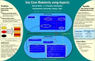
Vision- The project aims at developing a CASE tool to support an enhanced ADOM-UML variant of the ADOM approach. The CASE tool should provide the ability to define domain models and feature model, to map between feature models and domain models, to support the instantiation of application models and their refinement, and to validate Application models vs. corresponding domain models. The tool should support all UML diagrams, as well as, incorporating OCL constraints.
The Problem Domain Domain analysis deals with identifying stakeholders and their objectives in a domain, defining selection criteria, identifying boundary conditions, examples, counter examples, main common features, and variants of the domain, defining relations to other domains, dividing the domain into sub-domains, acquiring domain information from experts, legacy systems, literature, and prototyping, describing domain terminology, and building overall domain models.
All existing techniques usually guide the application designer of how to select the required features, while validation is supported by checking whether the feature constraints defined in the domain model hold in the specific application. However, the main limitation of these methods is that they allow closed variation points and do not support adding new application-specific features which were not modeled within the domain, affecting on the completeness of the created application models.
The Application-based Domain Modeling (ADOM) The Application-based DOmain Modeling (ADOM) approach is based on a three layered framework, which is embedded within the classical framework for meta modeling presented in OMG-MOF (2003). • The application layer, which is the lowest layer, consists of models of particular applications, including their structure (scheme) and behavior. • domain layer consists of specifications of various domains, such as web applications, multi agent systems, and process control systems. • The language layer comprises of metamodels and specifications of modeling languages,UML2.0 in the case of ADOM-UML.
ADOM Benefits: ADOM, which can be classified as a meta modeling domain analysis approach, has the following three main advantages over other domain analysis methods: • It provides a complete method that focuses on two of the main usages of domain models: creating and validating application models according to their corresponding domain models, • It utilizes to the fullest the expressiveness of the modeling language(UML)in particular, it uses the same languages and techniques for the application and domainlayers, enables structural and behavioral specifications of domains, and bridges the gaps between the abstraction levels of these layers • It does not depend on a specific modeling language rather it can easily be adapted to different modeling languages with small changes (if any) to their specification or meta model.
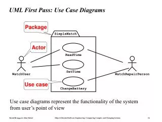
The Unified Modeling Language (UML) • UML is a graphical language for visualizing, specifying and constructing the artifacts of a software-intensive system. • UML combines the best practice from data modeling concepts such as entity relationship diagrams, work flow, object modeling and component modeling.
The Object Constraint Language (OCL) • The Object Constraint Language is a declarative language for describing rules that apply to UML models developed at IBM and now part of the UML standard.
Feature Modeling Feature models are a well accepted means for expressing requirements in a domain on an abstract level. They are applied to describe variable and common properties of products in a product line, and to derive and validate configurations of software systems.The feature model techniques aims at capturing the features applicable to a specific domain. The feature model serves as an external point of view of the system and should help the designer to capture the system internal structure (and functionality).
Software Context The development of the intended CASE tool will be based on the Eclipse Modeling Framework and an open source UML-based CASE tool developed on top of that framework.
EMF • EMF is a modeling framework and code generation facility for building tools and other applications based on a structured data model. • From a model specification described in XMI, EMF provides tools and runtime support to produce a set of Java classes for the model. • In order to create this XMI, EMF provides an Ecore editor, which let us build Ecore diagrams, that represent the model we want to build and generate.
GEF - Graphical Editing Framework The Graphical Editing Framework (GEF) allows developers to create a rich graphical editor from an existing application model. TOPCASED Topcased is an integrated System/Software engineering toolkit compliant with the requirements of critical and embedded applications.
Functional Requirements • Creation of domain models. • Creation of Application Models. • Validation of an application model with respect to a domain model. • Creation of feature models. • Mapping features and models. • Association of ADOM classifiers to the features models. • Instantiating feature models . • Validate Models .
Performance constraints • The following non-functional requirements are applicable • for the project: • Each modeling operation should be ended in one second. • Instantiation should be completed at the most in 5 seconds. • Validation Should be completed in 5 seconds • With future prospective our Code system should be modular; allowing later changes, modifications and add-ons.
Stereotypes Stereotypes allow you to extend the vocabulary of the UML so that you can create new model elements, derived from existing ones, but that have specific properties that are suitable for your problem domain. They are used for classifying or marking the UML building blocks in order to introduce new building blocks that speak the language of your domain and that look like primitive, or basic, model elements.
Tagged Values Tagged values are properties for specifying keyword- Value pairs of model elements, where the keywords are attributes. They allow you to extend the properties of a UML building block so that you create new information in the specification of that element. Tagged values its value applies to the element itself and not to its instances.
Constraints Constraints are properties for specifying semantics and/or conditions that must be held true at all times for the elements of a model. They allow you to extend the semantics of a UML building block by adding new rules, or modifying existing ones.