Download
1 / 81
860 likes | 1.11k Views
OO System Models UML Use Case Driven Object Modeling. Objective. Introduce the requirements view of a system Explain the sections of a use case text Provide the student with a template for writing the use case description Introduce the use case and context diagrams

E N D
OO System Models UML Use Case Driven Object Modeling
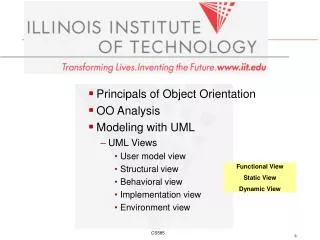
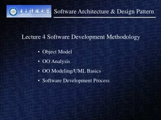
Objective • Introduce the requirements view of a system • Explain the sections of a use case text • Provide the student with a template for writing the use case description • Introduce the use case and context diagrams • Describe the artifacts used with a Use Case • Explain a logic via artifacts decision tables or decision tree • Explain use cases relations, e.g., include, extend, generalise
Work backwards from code • Do a little prototyping, • and start to write some use cases. ?
Design-levelclass diagram Before getting to code: • Get design-levelclass diagram (details): • All attributes and operations (methods), visibility,.. • Relationships (generalization, association, aggregation, composition) • Note: • Analysis-level class diagram includes all classes but with less details on attributes and operations
How to get Design-Level Class Diagram . Design-level class diagrams serve as the structure for the code ?
How to get Design-Level Class Diagram • Draw sequence diagrams to allocate methods to classes • We need to allocate behavior into classes • Sequence diagrams help you decide which classes are responsible for which methods • Draw a sequence diagram for each usecase scenario (sequence of steps)
Sequence Diagrams Allocate methods to classes as you draw sequence diagrams . ? Dynamic model Static model
Before you do sequence diagrams.. You need to have a good idea about: • what objects will be performing in which use case, • what functions the system will perform as a result of user actions.
UML Use Case Model “Requirements View”
USE CASE ‘Usage Case’ Use case • Equivalent to requirements • Discover and record functional requirements - stories of using a sys • Use cases are text docs Use case diagrams: UML defines UC diag to show: • the names of Ucs & actors, • their relationships – • may be used as contract doc with sys customer • In UML UCs are the driver for the rest of the diagrams of UML. • UC should focus on the question “ How can using the sys provide observable value to the user, or fulfill their goals
UC Diagram – Modeling the Context of a System • Components: • System: rectangle • Actors: outside the system rectangle (external to the system) • Use Cases: inside the system rectangle • Actors • People interacting with the use case • Other sys interacting with the UC • Hardware,… • An actor needs not to initiate the UC; association shows actor involvement
optional ATM subsystem Withdraw cash Check balance Customer (actor role name) Print statement Use case diagram for ATM subsystem
Use Case Model • Use Case diagram • Use Case Text (description) • Use Case Text • Use case name • Pre-conditions • Normal (Basic) flow of events –Happy path • Alternatives - Exceptional flows • Post-conditions:
Use Case model • Shows User–Systeminteraction across the system boundary • Actors interact with the system as a whole (not with some specific part of it) • System is viewed as a black box • Defines software boundaries • Shows functional requirements
Actor-Goal list • Ex: POS system Important: Be suspicious if you can’t find primary actors (as external computer sys, …) Sales activity system is a remote application that will frequently request sales data from each POS node on the network
Use Case Diagram System name Use Case Diagram
System Name UC A Another System Customer UC B UC C Admin Individual Corporate UC D UC Diagram
Use Case Text (description) Format • One-column format • Two-column format • Prefer two-column format: clearly shows Actor action and system response • For each step: Actor does x (or system does y)
Use Case Text: Sections • Name • ID • Primary actor • Stakeholders • Goal • Priority • Risk • Trigger • Relationships: Association, Includes, Extends
Use Case Text: Sections (cont.) • Input • Pre-conditions • What validity checks or constraints apply on the inputs (or the internal system as a whole, in some cases) • Normal (Basic) flow of events – Happy path –Successful path - Main Success Scenario • Alternatives: successful scenarios • Exceptional flows: failure • Post-conditions: • What changes does the Use Case make to the internal system state • Output • Test Cases: Unit tests and functional tests • Use Case Points UCP: for cost estimation extensions
Use Case Text - Extensions • For alternatives or additions to the main success scenario • Scenario: sequence of steps • Each extension is described separately • Each extension describes a new UC that extends the main UC • The last step in an extension may be: • Fail: UC goal unsatisfied • Stop: UC goal satisfied • Resume n: Continue with next step n in the main scenario
Brief Use Case Example: • Use Case: Identify Client • Primary Actor: Client • Trigger: Client inserts his ATM (Automatic Teller Machine) card • Goal: The intention of the Client is to identify him/herself to the System. A project (operational) constraint states that identification is made with a card and a personal identification number (PIN). • Basic (Normal) Flow “Successful Scenario”, “Happy Path” • Alternate Flows “Extensions”: leads to successful use case • Exceptional Flows: leads to failure of use case
Basic Flow “Successful Scenario”, “Happy Path” – One column format Basic Flow “Successful Scenario”, “Happy Path”: 1. Client provides Card Reader with card. 2. System validates card type. 3. Client provides PIN to System. 4. System requests BAT System to verify identification information*. 5. BAT System informs System that identification information is valid, and System informs Client.
Basic Flow “Successful Scenario”, “Happy Path” – Two- column format • Two- column format: conversational • Example: • Use the format you are comfortable with.
Extensions Example of Extensions Flows: Failure / Success / Resume (1-6)a. (at any time) Client cancels the identification process. (1-6)a.1. System requests Card Reader to eject card; use case ends in failure. 2a. System ascertains that card type is unknown: 2a.1. The System informs the Client and requests the Card Reader to eject the card; the use case ends in failure. 2b. System informs Client that it is currently "out of service": use case ends in failure. 3a. System times out on waiting for Client to provide PIN: 3a.1. System requests Card Reader to eject card; use case ends in failure.
Alternative Flows 5a. BAT System informs System that password is incorrect: 5a.1. System informs Client and prompts him/her to retry; use case continues at step 3. 5a.1a. System ascertains that Client entered an incorrect PIN for the third time: 5a.1a.1. System swallows card and informs Client to see Bank for further details; use case ends in failure. 5b. BAT System informs System that card information is invalid: 5b.1. System informs Client and requests Card Reader to eject card; use case ends in failure. 5c. System is unable to communicate with BAT System: 5c.1. System informs Client that it is now out of service and requests Card Reader to eject card; use case ends in failure**.
Extension: Alternative & Exceptional Flows Extensions Alternative flow UC Success UC Failure Exceptional flow
Extension: Alternative & Exceptional Flows An extension may be: • An exceptional flow leading to failure of the use case • An alternative flow leading to success of the use case • exceptional flow
UC Diagram: The 4 types of associations / relationships
UC Diagram: The 4 types of associations / relationships • Generalisation between: • actors • use cases • Include relationship between use cases • Extend relationship between use cases
Generalisation between use cases • Like generalization among classes • A child UC inherits the behaviour & meaning of the parent UC • The child UC may add to or override the behaviour of its parent UC • The child UC may be substituted any where the parent UC appears ( both parent & child UCs may have concrete instances) • Is often implemented by inheritance
General UC Parent UC Child UC Specialised UC Concrete UC Generalisation between use cases:
Italic= = abstract UC Register car sharer Transfer car sharer info from web server web server Manually add car sharer Car match administrator Generalisation between use cases: Abstract UC • Abstract UC: • general UC that will never exist in a real sys • it defines what is common to specialized UCs • name in italicor using {abstract}
Customer Individual Corporate More general actor role name Specialised actor role name Generalisation between Actors
Register Car Sharer Match Car Sharer Franchisee Record sharing agreement Car match administrator Produce performance report Accountant Example: No generalisation between actors
Same ex with Generalisation between actors More general actor with role name ‘Car match administrator’ Register Car Sharer Match Car Sharer Car match administrator Record sharing agreement Generalisation between actors Produce performance report Accountant Franchisee Actor Franchisee can do any thing actor Car match administrator can do and more (Produce performance report)
Include Relationship between Use Cases • Mandatory Behaviour • One UC always includes another • A base UC explicitly include the behaviour of another UC at a location specified in the base UC • Encapsulate some functionalities in the included UC that is used at several points (avoid repetition) • UC A ‘include” (or “use”) UC B
Stereotype base UC A “include” “use” Including UC A Included UC B Include Relationship between Use Cases • UC A ‘include” (or “use”) UC B
Include Relationship between Use Cases • Mandatory Behaviour: ‘Buy Goods’ use case always includes ‘Identify User’ use case
Extends Relationship between Use Cases • Optional behavior • ‘Buy Newspaper’ UC Optional extends the behavior of ‘Going To Work’ UC (at a specified location within ‘Going To Work’ UC).
EBP: Elementary Business Process EBP is a process: • performed in response to business event • adds measurable business value • leaves the data in consistent state Ex: • Register course • Drop course • Process sale • Issue PO • A UC represents a complete functionality serving a goal for the actor • Set of actions; not a single action • Do not include UCs such as: delete an item, add new item, etc…
Artifacts used with a Use Case Artifact: is a man-produced work-product: • Pseudo code • Table • Database schema • Text document • Diagram • Models • Web graphic • Test case • etc
Artifacts used with a Use Case • A use case may be supplemented with one or more artifacts- links to explain an issue • A decision logic needs to be documented • Example: decision logic for grading • if mark >= 95 then grade = A+ • if mark >= 90 and < 95 then grade = A • …..
Artifacts for Logic Modelling Logic Modelling of a step within use case scenario is expressed via artifacts: • Structured English - Psuedo code • Decision Tables • Decision Trees
Logic Modelling: Decision Tables Reads: If C1 AND C2 then Action Ai
i=m i=1 Logic Modelling: Decision TablesNumber of rules If • C1 has n1 values • C2 has n2 values • ........ • Ci has ni values • ……. • Cm has nm values Number of rules = n1x n2 x … x ni x…x nm = (ni)
Logic Modelling: Decision Tables How to create a decision table • Name the condition and values each condition can assume • Name all possible actions that can occur • List all rules • Define the actions for each rule • Simplify the table