Download
1 / 26
280 likes | 493 Views
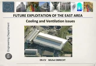
CLIC WORKSHOP - 2008. COOLING AND VENTILATION IN THE TUNNEL. J. Inigo-Golfin - C. Martel CERN TS/CV Wednesday 15 th October 2008. CLIC WORKSHOP - 2008. This is a preliminary study. Some concepts are presented based on estimated values to be confirmed.

E N D
CLIC WORKSHOP - 2008 COOLING AND VENTILATION IN THE TUNNEL J. Inigo-Golfin - C. Martel CERN TS/CV Wednesday 15th October 2008
CLIC WORKSHOP - 2008 This is a preliminary study. Some concepts are presented based on estimated values to be confirmed. The confirmation of rate air/water is still standing. Cooling Ventilation • Ventilation functions- Heat load levels- HVAC principle - Tunnel section- Safety - Equipment - Perspectives • Water cooling requirements- Fluid circuits - Cooling principle - Main cooling station- Tunnel section. Piping- Equipment - Perspectives
CLIC WORKSHOP - Ventilation Tunnel ventilation functions • Fresh air for people and ventilation (obligation).- Requested ambient conditions (T°C and humidity).- Remove heat loads in the air.- Prevent from any air stratification, condensation. - Purge before access.- Smoke or gas extraction (obligation).- Overpressure control linked to radiation (obligation).
CLIC WORKSHOP – Ventilation Heat loads in the air Drive Beam sector = 250 kW UTRA cavern = 200 kW Loop = 90 kW UTRA 200 kW LOOP 90 kW 250 kW Heat loads in the Loops & UTRA: 290 kW / DB sector 1450 kW between two shafts Heat loads in the tunnel: 250 kW / DB sector 1250 kW between two shafts
CLIC WORKSHOP - Ventilation HVAC of underground areas Loop • Three systems: • Tunnel • UTRAs • LOOPs 90 kW UTRA 200 kW Local cooling production
CLIC WORKSHOP - Ventilation Tunnel Air flow rate considerations Tunnel section = 20 m2 DB sector volume =17 000 m3 Inter shaft volume = 90 000 m3 Basic data: Delta Temperature (Extraction – Supply) = 28 – 18 = 10°C Air flow rate Air duct section Heat loads in the tunnel Air duct Diameter 250 kW 1250 kW 500 kW 75 000 m3/h 370 000 m3/h 150 000 m3/h 1.73 m2 8.56 m2 3.3 m2 1.48 m 3.3 m 2 m DB sector Input data Intershafts Intershafts Proposal To be Optimised …
CLIC WORKSHOP - Ventilation Tunnel Air handling from the surface HVAC equipment in surface buildings Air supply Extraction Air supply Extraction
CLIC WORKSHOP - Ventilation Semi transversal ventilation in tunnel Extraction Air supply Extraction Air supply Optimisation of the air flow rate. Low air speed in the tunnel < 0.1 m/s. Optimisation of the temperature gradient. Recycling of the tunnel air possible. Reversible operation possible. Energy recovery possible. NEXT SHAFT POINT SHAFT POINT
CLIC WORKSHOP - Ventilation Semi transversal ventilation in tunnel Extraction Air supply Extraction Air supply Possible fire resistant sectors, with 2 emergency exits per sector NEXT SHAFT POINT SHAFT POINT Minimum maintenanceSealed, modulatedFire resistantCompressed air control 1 Smoke extraction trap per sector 1 supply and 1 extraction grilles per 30 m
CLIC WORKSHOP - Ventilation Safety considerations Extraction Air supply Extraction Air supply SHAFT POINT • Control of the pressure from both ends of a sector. • Control of the pressure (overpressure or underpressure in each area). • Fire detection per sector compatible to fire fighting via water mist.
CLIC WORKSHOP - Ventilation Tunnel section SUPPLY DUCT EXTRACTION DUCT Circuit C : Fire Fighting Circuit B : general cooling Circuit D : compressed air Circuit A : Module cooling This cross section is for study purposes only Approved CLIC tunnel Diameter is currently 4.5m
CLIC WORKSHOP - Ventilation Equipment issuesNot standard industrial fans High pressure fansAdapted products Not standard equipment
CLIC WORKSHOP - Ventilation Equipment issuesSpecial design Extraction unit Fan in specific concrete section Concrete air ductsDirect driven fans (no belts)Fan in specific concrete section Concrete sound attenuation Supply unit 6000
CLIC WORKSHOP - Ventilation Perspectives • Heat loads in tunnel air to optimize- Heat loads in Exp. caverns, Klystrons to be defined?- Radiation levels in the various areas to be defined- Integration of ventilation ducts in the tunnel section to finalize
CLIC WORKSHOP - Cooling Cooling • Water cooling requirements- Fluid circuits - Cooling production - Main cooling station- Tunnel section. Piping- Equipment considerations- Perspectives
CLIC WORKSHOP - Cooling Water cooling requirements Modules cooling (circuit A) Modules total power: 70 MW Required flow-rate: 3215 m3/h Delta temperature: 20 K Temp. Supply: 25 °C
CLIC WORKSHOP - Cooling Water cooling requirements General cooling (circuit B) Dump Dump 1000 kW 1000 kW 1000 kW 0 kW ? Loop 1000 kW Loop 0 kW ? UTRA UTRC Modules total power: 15 MW Required flow-rate: 1612 m3/h Delta temperature: 8 K Temp. Supply: 27 C
CLIC WORKSHOP - Cooling Fluid circuits per side • CIRCUIT A : MODULES COOLING – 70 MW Demineralised water, 25/45°C, 2 pipes Ø600 Accelerator structure, Loads, PETS, Quadripoles • CIRCUIT B : GENERAL COOLING – 15 MW Demineralised water, 27/35°C, 2 pipes Ø300 UTRA, UTRC, Loop, Vacuum, Beam Dump • CIRCUIT C : FIRE FIGHTING - Water mist – Ø80 • CIRCUIT D : REGULATION Compressed Air – 760 m3/h, Ø150, 8 bars - For solids (dust): class 1 with max. 0.1 mg/m3 - For water : class 2 with -40°C dew point - For oil : class 1 with max. 0.01 mg/m3
CLIC WORKSHOP - Cooling Raising circuits Raising pumps Tunnel section Drain
CLIC WORKSHOP - Cooling CoolingProduction Pumping station
CLIC WORKSHOP - Cooling Main Cooling station WATER MIST CIRCUIT A CIRCUIT B M ~ N+1 Main Linac Z.E. ? MW ? MW 11 EXCHANGERS 10 MW ? 2 m Back to lake From lake
CLIC WORKSHOP - Cooling Tunnel section. Piping Circuit C : Fire Fighting Circuit B : general cooling Circuit D : compressed air Circuit A : Module cooling This cross section is for study purposes only Approved CLIC tunnel Diameter is currently 4.5m
CLIC WORKSHOP - Cooling • Out of standard pipe diameters- Special tooling, welding process- On request manufacturing, PN an issue?- Extra large heat exchangers Equipment considerations 6 MW Heat Exchanger 3.2 m 1.8 m 1.2 m
CLIC WORKSHOP - Cooling Missing items affecting main cooling station • Cooling power for experimental cavern ?- Cooling power for Main dumps- HVAC and cooling for klystrons- Confirmation about the rate air/waterOther items to be considered:- Fire-fighting flow-rates- Infiltration water, raising pumps, slopes
CLIC WORKSHOP - 2008 Longitudinal principle Extraction Air supply NEXT SHAFT POINT SHAFT POINT Large air flow rate High speed Temperature gradient Base: 150 000 m3/h 1250 kW Delta T°C = 24 = (41-17) Air speed = 2 m/s