Download
1 / 37
370 likes | 459 Views
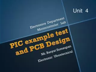
Information Engineering and Technology . Electronics Department. Microcomputer Applications. PIC example test and PCB Design. Dr. Amr Talaat. Abdulrahman Abdul- Munsif . Introduction.

E N D
Information Engineering and Technology Electronics Department Microcomputer Applications PIC example test and PCB Design Dr. Amr Talaat Abdulrahman Abdul-Munsif
Introduction PIC Microcontrollers are very advanced devices used in many embedded systems applications in our daily life applications
Outline • Hardware requirements for PIC • PIC diagram and implementation • PIC example on bread board • PCB Design Introduction • PCB design steps • Step (1) :Eagle CADSOFT software installation • Step (2) :Eagle CADSOFT Schematics • Step (3) :Eagle CDSOFT Layouts • Basics in Eagles • Assignment (2)
(1) Hardware REQ. for PIC 40 pins PIC Microcontrollers 16f877a Breadboard for testing / Cupper Plate for PCB Voltage regulator LM7805 4 MHz Crystal Oscillator 40 pins Connector for the PIC Microcontrollers Jumpers Batteries generating DC voltage Capacitors 22u Farrad Resistors 10k ohm LEDs with different colors for testing
Outline • Hardware requirements for PIC • PIC diagram and implementation • PIC example on bread board • PCB Design Introduction • PCB design steps • Step (1) :Eagle CADSOFT software installation • Step (2) :Eagle CADSOFT Schematics • Step (3) :Eagle CADSOFT Layouts • Basics in Eagles • Assignment (2)
(2) PIC Diagram PIC Microcontrollers Pins Layout
(2) Cont. The implemented schematic diagram
(2) Cont. The final Circuit implementation on bread board
Outline • Hardware requirements for PIC • PIC diagram and implementation • PIC example on bread board • PCB Design Introduction • PCB design steps • Step (1) :Eagle CADSOFT software installation • Step (2) :Eagle CADSOFT Schematics • Step (3) :Eagle CADSOFT Layouts • Basics in Eagles • Assignment (2)
(3) PIC Example Write a C program to flash / blink LEDs #include <16f877A.h> ; #use delay (clock = 1000000) #fuses XT , noput voidmain(void) { while(1) { output_high(PIN_B7); delay_ms(1000); output_low(PIN_B7); delay_ms(1000); } } // download the HEX file on the pic via the programmer and testing the blinking of LEDs
Outline • Hardware requirements for PIC • PIC diagram and implementation • PIC example on bread board • PCB Design Introduction • PCB design steps • Step (1) :Eagle CADSOFT software installation • Step (2) :Eagle CADSOFT Schematics • Step (3) :Eagle CADSOFT Layouts • Basics in Eagles • Assignment (2)
(4) PCB Design • PCBis used to mechanically support and electrically connect electronic components using conductive pathways, tracks or signal traces etched from copper sheets laminated onto a non-conductive substrate. It is also referred to as printed wiring board (PWB) or etched wiring board. • PCB Design is much better and having many advantages • 1) Clear design • 2) Make design away from short circuits • 3) Make inexpensive design • 4) Make Highly reliable design • 5) Faster design for high volume production
(4) Cont. PCBis considered better than the design on bread board and more reliable without jumping wires and extensions that could be a reason for the short circuit (SC), so the bread board could be a way to test the hardware but could not be considered as final implementation
Outline • Hardware requirements for PIC • PIC diagram and implementation • PIC example on bread board • PCB Design Introduction • PCB design steps • Step (1) :Eagle CADSOFT software installation • Step (2) :Eagle CADSOFT Schematics • Step (3) :Eagle CADSOFT Layouts • Basics in Eagles • Assignment (2)
(5) PCB Design steps PCBhas many steps required for its design Make the schematic and design on EAGLE CADSOFT Print Design on two transparent papers with actual size of design Stick the two papers perfectly together Put it in the UV light machine and vacuum the air everywhere
(5) Cont. 5) Take it directly to the developer solution and drop it many times inside it till all photoresist will be removed and the patterns of wires appear( from 1 - 2 mins) 6) Then put it inside the etching solution to get rid of all not needed copper and only remains the needed copper for wiring ( from 15 – 20 mins) and at 50 degrees
(5) Cont. 7) Check under microscope if it contains short circuits (SC) or with Multimeter and if there is any short circuits etch it again till all is gone 8) Then put is again in UV light machine to get rid of all photoresist 9) Make holes required for the design by the drilling machine size 10) Start soldering ICs in its suitable places according to your design
(5) Cont. These steps are required to design PCB and it should be done in reality .. But for simplicity hand out your design and you will get it printed and ready for soldering and integrating ICs on it. Soldering process will be discussed later in details
Outline • Hardware requirements for PIC • PIC diagram and implementation • PIC example on bread board • PCB Design Introduction • PCB design steps • Step (1) :Eagle CADSOFT software installation • Step (2) :Eagle CADSOFT Schematics • Step (3) :Eagle CADSOFT Layouts • Basics in Eagles • Assignment (2)
(6) EAGLE S/W installation Eagle is a very professional tool for designing PCBs and allow the designer to import some of the design rule check of a manufacturer that will implement the in reality Eagle is also giving options to the designer to create schematic for the circuit and design for best layout PCB board by routing wires either on one side or both sides to generate double sided PCBs.
(6) Cont. Eagle has a good introduction and demo could be downloaded from the following link http://www.cadsoftusa.com/downloads/?language=en Eagle has many version for mac OSX, Linux and windows, and the installation could be revised in case of any problems Version 5.11 DEMO is available on the download links Eagle design rule check could be downloaded from the PCB-POOL website to consider the design limitations http://www.pcb-pool.com/ppuk/service_specifications.html Eagle has many extra tutorials on the same webpage, read the PDF for extra knowledge http://www.piclist.com/images/www/hobby_elec/e_eagle20.htm#2 http://www.hcilab.org/resources/boardlayout/eagle-librarydesign.htm
Outline • Hardware requirements for PIC • PIC diagram and implementation • PIC example on bread board • PCB Design Introduction • PCB design steps • Step (1) :Eagle CADSOFT software installation • Step (2) :Eagle CADSOFT Schematics • Step (3) :Eagle CADSOFT Layouts • 9) Basics in Eagles • 10) Assignment (2)
(7) EAGLE Schematics Eagle Schematic is away to represent the circuit diagram in a certain way to be represented simply after that on a PCB Main menus toolbar Schematic area Toolbox
(7) Cont. Eagle Schematic functions Grid adjust Cut Bus Redraw Show Wire Zoom out Information Generate board Zoom in Layers Add text Fit to design Copy Add value Print Move Add Name Open Mirror Add part Save Rotate Delete Paste Redo Group Settings Undo Select
Outline • Hardware requirements for PIC • PIC diagram and implementation • PIC example on bread board • PCB Design Introduction • PCB design steps • Step (1) :Eagle CADSOFT software installation • Step (2) :Eagle CADSOFT Schematics • Step (3) :Eagle CADSOFT Layouts • Basics in Eagles • Assignment (2)
(8) EAGLE Layouts Eagle Layout is a way to represent the eagle schematic in a finalized layout of a PCB which will be printed on it Main menus toolbar Layout Area Toolbox
(8) Cont. Eagle Layout functions Grid adjust Cut Octagon Hole Round Hole Show Wire Square Hole Information Return to sch. DRC Layers Add text Route Wires Copy Add value Delete Route Move Add Name Open Mirror Add part Save Rotate Delete Paste Errors Group Settings Hole in PCB Ratsnest
Outline • Hardware requirements for PIC • PIC diagram and implementation • PIC example on bread board • PCB Design Introduction • PCB design steps • Step (1) :Eagle CADSOFT software installation • Step (2) :Eagle CADSOFT Schematics • Step (3) :Eagle CADSOFT Layouts • Basics in Eagles • Assignment (2)
(9) Basics in Eagle DIL Package It is the package that allows the usage of devices with Pins and holes on the PCB SMD Package It is the package that allows the usage of Surface Mount Devices on the PCB
(9) Cont. Important Rules While designing If it is available for you to use connectors go on Always check DRC while working to know exactly where is your error Always use the name and the value of any element to make your design clear and prepared well for soldering Try to compress the area of your design as possible Make always capacitors between higher and lower Voltage supplies Make the Power signal and ground more thick in the design to be distinguished from wires of signals
(9) Cont. Important Rules While designing Use capacitors beside the connectors Make shorter paths and try to lower the number of crossing wires and try first to do your best for fitting your design on one-sided PCB, After than think about the other possibilities because it is more expensive After finishing your design create a ground plane which means anything else except for the signals, power lines will be considered ground Area you will work on will be given in the project document and instructions
(9) Cont. Topics discussed while working on EAGLE in LAB Adjust working directories for Files, projects and libraries Adding libraries to eagle library Add elements to eagle library from its data sheet with real physical dimensions Printing your design Change elements through layers like texts
(9) Cont. LAB EXAMPLE
Outline • Hardware requirements for PIC • PIC diagram and implementation • PIC example on bread board • PCB Design Introduction • PCB design steps • Step (1) :Eagle CADSOFT software installation • Step (2) :Eagle CADSOFT Schematics • Step (3) :Eagle CADSOFT Layouts • Basics in Eagles • Assignment (2)
(10) Assignment (2) Start designing the PIC MICROCONTROLLER Circuit in the project description on eagle cadsoft and hand it out next time
Thanks Dr. Amr Talaat Abdulrahman Abdul-Munsif