Download
1 / 7
70 likes | 185 Views
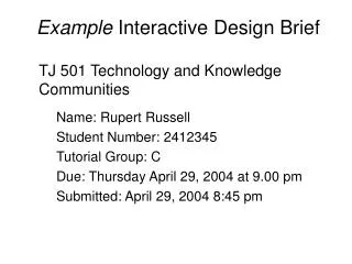
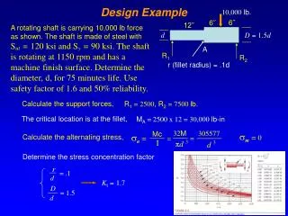
Design Example. The 10” TH. wall system shown in the figure below is to be checked for a service gravity load of 3 Kips/ft and a lateral load of 25 Kips, acting in plane to the wall. The lintel bearing is as per SBC 07.

E N D
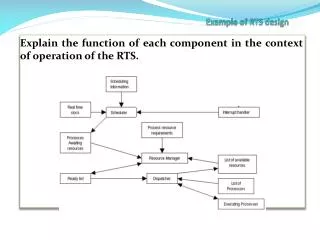
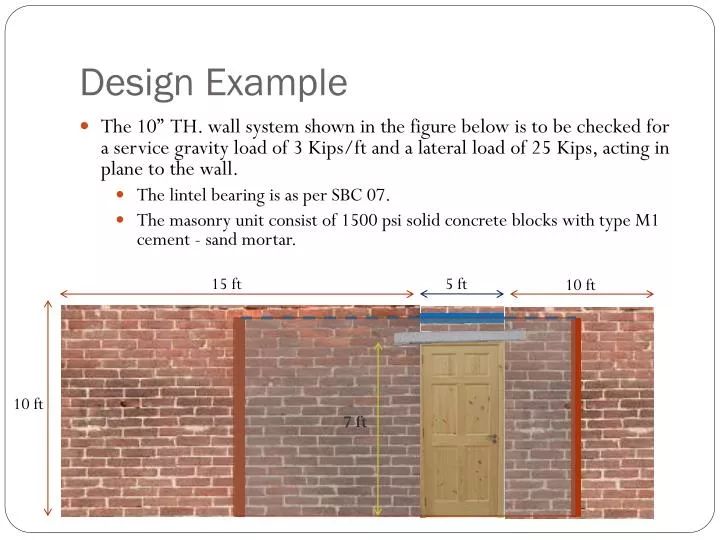
Design Example • The 10” TH. wall system shown in the figure below is to be checked for a service gravity load of 3 Kips/ft and a lateral load of 25 Kips, acting in plane to the wall. • The lintel bearing is as per SBC 07. • The masonry unit consist of 1500 psi solid concrete blocks with type M1 cement - sand mortar. 15 ft 5 ft 10 ft 10 ft 7 ft
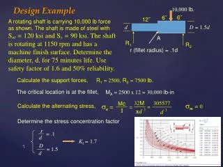
Analysis (Masonry Frame Properties) • W1: • Cross-Section Area = 10” x (15’x12) = 1800 sq.in. • Inertia = 10” x (15’x12)^3 / 12 = 4860000 in4. • Weight = 0.144 x (1800 / 144) x 10” = 18 Kips • Load from slab = 3 x 15’ = 45 Kips • W2: • Cross-Section Area = 10” x (10’x12) = 1200 sq.in. • Inertia = 10” x (10’x12)^3 / 12 = 1440000 in4. • Weight = 0.144 x (1200 / 144) x 10” = 12 Kips • Load from slab = 3 x 10’ = 30 Kips • Beam: • Cross-Section Area = 10” x (3’x12) = 360 sq.in. • Inertia = 10” x (3’x12)^3 / 12 = 38880 in4. • Weight = 0.144 x (360 / 144) = 0.36 Kips / ft 45 kip 30 kip 3 + 0.36 Kips /ft 25 Kips 10 ft W1 W2 5 ft
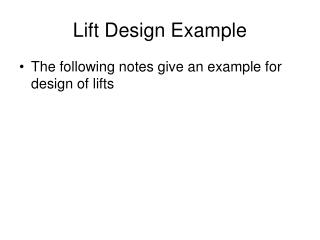
Analysis Results Bending Moment (K.ft) Shear Force (K) Axial Force (K)
Wall 1 Section 9.6.6.1 (Table 9-b) • Compressive stress: • P/A = (45+24.7) / 1800 = 0.0387 Ksi or 38.7 psi • Basic compressive stress = 0.96 MPa or 139.23 psi • Slenderness ratio = H/W = (10x12)/10 = 12 • ks = 0.84 • Area of element = 1800/144 = 12.5 sq. ft (>2.5 sq. ft) • ka = 1 • Assuming height of a unit as 6 in & 10 in width: height to width ratio = 6/10 = 0.6 (<0.75) • kp = 1 • Allowable compressive stress = ks kakp x Basic compressive Stress 0.84 x 1 x 1x 139.23 = 116.9 psi (OK) • Flexural Stresses: • P/A + My/I = 0.0387 + (199x12)(7.5x12)/4860000 = 0.0809 Ksi or 80.9 psi • P/A - My/I = 0.0387 - (199x12)(7.5x12)/4860000 = -0.0035 Ksi or 3.5 psi • Allowable compressive stress = 116.9 psi (OK) • Allowable tensile stress = 20 psi (OK) • Shear Stresses: • V/A = 19.7 / 1800 = 0.0109 Ksi or 10.9 psi • Allowable stress = fs = 0.1+fd/6 = 0.1 + (38.7x0.0068)/6 = 0.1155 MPa or 16.75 psi (OK) Section 9.6.6.1.1 (Table 9-b) Section 9.6.6.1.2 (Table 9-b) Section 9.6.6.1.3 (Table 9-b) Section 9.6.6.2 Section 9.6.6.3
Wall 2 Section 9.6.6.1 (Table 9-b) • Compressive stress: • P/A = (30+22.1) / 1200 = 0.0434 Ksi or 43.4 psi • Basic compressive stress = 0.96 MPa or 139.23 psi • Slenderness ratio = H/W = (10x12)/10 = 12 • ks = 0.84 • Area of element = 1200/144 = 8.33 sq. ft (>2.5 sq. ft) • ka = 1 • Assuming height of a unit as 6 in & 10 in width: height to width ratio = 6/10 = 0.6 (<0.75) • kp = 1 • Allowable compressive stress = ks kakp x Basic compressive Stress = 0.84 x 1 x 1x 139.23 = 116.9 psi (OK) • Flexural Stresses: • P/A + My/I = 0.0434 + (42.4x12)(5x12)/1440000 = 0.0646 Ksi or 64.6 psi • P/A - My/I = 0.0434 - (42.4x12)(5x12)/1440000 = -0.0222 Ksi or 22.8 psi • Allowable compressive stress = 116.9 psi (OK) • Allowable tensile stress = 20 psi (OK) (No Tensile Stresses) • Shear Stresses: • V/A = 5.3 / 1200 = 0.0044 Ksi or 4.4 psi • Allowable stress = fs = 0.1+fd/6 = 0.1 + (18.4x0.0068)/6 = 0.120 MPa or 17.4 psi (OK) Section 9.6.6.1.1 (Table 9-b) Section 9.6.6.1.2 (Table 9-b) Section 9.6.6.1.3 (Table 9-b) Section 9.6.6.2 Section 9.6.6.3
Beam Section 9.6.6.1 (Table 9-b) • Compressive stress: • P/A = 5.3 / 360 = 0.0147 Ksi or 14.7 psi • Basic compressive stress = 0.96 MPa or 139.23 psi • Slenderness ratio = H/W = (5x12)/10 = 6 • ks= 1 • Area of element = 360 /144 = 2.5 sq. ft (=2.5 sq. ft) • ka = 1 • Assuming height of a unit as 6 in & 10 in width: height to width ratio = 6/10 = 0.6 (<0.75) • kp = 1 • Allowable compressive stress = ks ka kp x Basic compressive Stress =1 x 1 x 1x 139.23 = 139.23 psi (OK) • Flexural Stresses: • My/I = (10.6x12)(1.5x12)/38880 = 0.0588 Ksi or 58.2 psi • Allowable compressive stress = 116.9 psi (OK) • Allowable tensile stress = 20 psi (Not OK) (Provide reinforcement) • Shear Stresses: • V/A = 6.7 / 360 = 0.0186 Ksi or 18.6 psi • Allowable stress = fs = 0.1+fd/6 = 0.1 + (14.7x0.0068)/6 = 0.116 MPa or 16.82 psi (Not OK) (Inc. Section) Section 9.6.6.1.1 (Table 9-b) Section 9.6.6.1.2 (Table 9-b) Section 9.6.6.1.3 (Table 9-b) Section 9.6.6.2 Section 9.6.6.3
Bearing Stress Check (Lintel) • Bearing length = 4 in or 1/10th of span • (5x12)/10 = 6 in (Take 6 in) • Bearing load = (3 + 0.36) x 5 / 2 = 8.4 Kips • Bearing area = 10 x 6 = 60 sq. in • P/A = 8.4/60 = 0.14 Ksi or 140 psi • Allowable Compressive stress = 139.23 psi (Not OK) • Bearing area with 30° inclination. = 10 x (6+6sin30)= 90 sq.in • P/A = 8.4/90 = 0.0933 Ksi or 93.3 psi • Allowable Compressive stress = 139.23 psi (OK) Section 9.6 Section 9.6