Download
1 / 21
210 likes | 359 Views
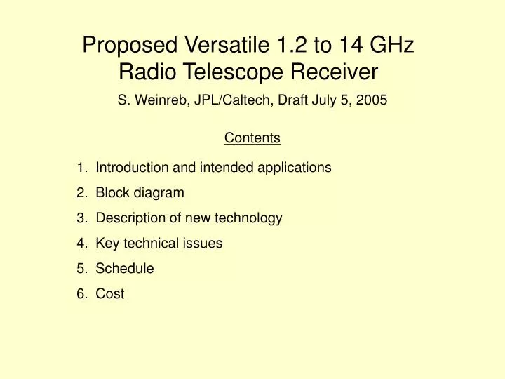
Proposed Versatile 1.2 to 14 GHz Radio Telescope Receiver. Contents. Introduction and intended applications Block diagram Description of new technology Key technical issues Schedule Cost. S. Weinreb, JPL/Caltech, Draft July 5, 2005. Introduction.

E N D
Proposed Versatile 1.2 to 14 GHzRadio Telescope Receiver Contents • Introduction and intended applications • Block diagram • Description of new technology • Key technical issues • Schedule • Cost S. Weinreb, JPL/Caltech, Draft July 5, 2005
Introduction • Technology developments during the past few years have made possible an extremely versatile and sensitive radio astronomy receiver with an instantaneous frequency range of 1.2 to 14 GHz in one instrument. • Advances in digital signal processing allow this entire frequency range to be analyzed during one integration period without frequency scanning. • These revolutionary technology advances greatly expand and facilitate the science which can be performed with a 34m radio telescope.
New Technology to be Described in This Proposal • Compact, efficient antenna feeds with decade or more frequency range have been developed at Chalmers University, Sweden • Low noise amplifiers also with decade bandwidth, < 10K noise at cryogenic temperatures, and differential input have been developed at Caltech • Microwave monolithic integrated circuits (MMIC’s) which facilitate downconversion to baseband. • Digital signal processors capable of analyzing 10 GHz of more of bandwidth at affordable costs
Measurements of a 1 to 13 GHz Model of a Dual Polarized Low-profile Log-periodic Feed for US-SKA Rikard Olsson1, Per-Simon Kildal2 and Sander Weinreb3 1,2Chalmers University of Technology, Göteborg, Sweden 3California Institute of Technology, Pasadena, California Abstract We present measured results for a dual polarized 1 to 13 GHz laboratory model of a feed for use in reflector antennas. The main goals of the laboratory model were achieved: it provides dual polarization and can provide more than a decade bandwidth. The aperture efficiency in a primary fed reflector system is greater than 56% over the entire band, and the input reflection coefficient of the feed is better than -5.5 dB. The results agree well with computed values.
Chalmers 1 to 13 GHz Feed Feed is currently being integrated with cryogenic LNA’s at Caltech.
Chalmers Feed Study Computed Results • Calculated pattern gives 57% prime focus efficiency, 3K spillover, and 0.3K mesh leakage in 12/16m symmetric antenna from 0.5 to 1.5 GHz • Gain is 10.5 +/- 0.5 dB and reflection coefficient better than 6 dB over 1:12 frequency range. Provides 65% efficiency at half-angles of 42O to 55O
Breadboard Feed/LNA Cryogenic SystemUnder Construction at Caltech
MMIC Wideband Low Noise Amplifiers Low-cost assembly MMIC package Amplifier provides 5K noise from 4 to 12 GHz when cooled to 12K Three-stage LNA in 2mm chip
Active Balun Function - Needed for Wideband Feeds A Microwave Low-Noise Cryogenic Differential Amplifier Wideband Feed with Output Balanced with Respect to Ground + Active Balun - Wideband antenna feeds have balanced output which cannot connect to a low-noise amplifier without a passive balun Passive baluns are large, lossy, and add noise to the system
WBAL2, 0.5-11 GHz active balun differential pair stage IN 2*1.6 mm chip size CMRR=gm*Rs (low frequencies) Requires matched components Same noise as a common source stage OUT
WBAL2 NGST InP HEMT MMIC Output microstrip Input lines from feed Active Balun-LNA on Carrier
Measured Active Balun Noise and Gain at 15KNoise peaks above 12 GHz are believed due to resonance in an input coupling capacitor and can be eliminated,
Key Technical Issues • Antenna efficiency and noise temperature • DSS28 has F/D of 0.3 which results in an 160O subtended angle at prime focus. With current Chalmers feed this would result in low spillover but with taper efficiency < 50%. • A Cassegrain system with an optimum subreflector for the wideband feed should be investigated • Continuum receiver sensitivity • Theoretical ΔT with Tsys = 30K, 1 GHz bandwidth, and 1 second integration time is .001K. It is difficult to achieve this theoretical sensitivity with a total power radiometer because of gain fluctuations and atmospheric noise fluctuation. • Digital spectrometer architecture • 1 GHz bandwidth is available with both autocorrelator and FFT processing. • Final mixing can either be I/Q or conventional baseband