Download
1 / 26
270 likes | 557 Views
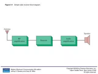
Digital Radio Receiver. Amit Mane System Engineer. Introduction. Virtually all digital receivers perform channel access using DDC The desired channel is translated using the digital mixer comprised of multipliers and DDS The sample rate is then adjusted to match the channel bandwidth

E N D
Digital Radio Receiver Amit Mane System Engineer
Introduction • Virtually all digital receivers perform channel access using DDC • The desired channel is translated using the digital mixer comprised of multipliers and DDS • The sample rate is then adjusted to match the channel bandwidth • CIC filter • Two poly phase decimators
Introduction • The functions performed in the system are • Waveform synthesis (DDS) • Complex multiplication • Multirate filtering • The overall sample rate change of the DDC is 120 • The DDS mixer has a SFDR of 102 dB • The data rate can be upto 208 MHz
Introduction • Innovative DRR System requires • One Quadia • Two UWBs • Number of channels implemented = 40
Digital Receiver Block Diagram 20 channels of I/Q @ 4.33 MSPS 32--bit DDR RAM 16Mx16 10 channels of I/Q @ 1.0833MSPS 16-bit A/D 12-bit 130/208 MSPS A UWB 1 of 2 A Clock DCM In = DSP1 EMIF Clk Out = DSP1 EMIF Clk A/D Intf Test Generator Quadia Logic 1 of 2 Dual Queue VFIFO 1 of 20 channels FIFO FIFO J4 Link 1 of 20 channels J4 link A/D Mux Mixer Gain Clock circuitry CIC 30:1 Test Mux CFIR 2:1 PFIR 2:1 Spectral invert Test Mux DSP Clk DSP1 Registers Data Flow Controller Overflow detect FIFO FIFO A/D Intf Interrupts Test Generator NCO A/D 12-bit 130/208 MSPS B 10 channels of I/Q @ 1.0833MSPS 16-bit Registers A/D input select Mixer Freq Rev Code Status Gain Test Register Test Controls 2-bit Register Spectral Inversion 20-bit DSP2 Registers DRR FIFO Thresh DSP Overflow detect Triggering Register Rev Codes Interrupts Clock DCM In = DSP2 EMIF Clk Out = DSP2 EMIF Clk Command Channel StatusRegister DCMs locked Reset PCI FPGA
MATLab SimuLink Development • MATLab and Simulink used with Xilinx System Generator • Simulink gateways provide connection to physical hardware and connect with Framework Logic • End-to-end simulation under MATLab • JTAG link allows real hardware to be tested from MATLab environment • System Generator links Xilinx tools for chip design
Using Simulink and System Generator • Simulink Block libraries are used to draw the system • Innovative BSP provides blocks for UWB components • Simulink blocks for DSP, data generation and viewing • Xilinx System Generator links all blocks Starting a new design!
Simulink Libraries • Board Support Package for CS includes hardware and signal processing components • A/Ds, J4, DDCs ....
SimuLink Block Diagram • The top level design has the Xilinx System Generator block for integration with logic tools Top Level Design
Xilinx System Generator Integrates with Simulink • Compiling and fitting the design is done directly from the Simulink environment
Design Using Simulink Blocks and Functions • Large libraries of DSP and logic function may be directly used • Drag-n-drop from Simulink libraries
Validating the Design • Validate the design by including the hardware in the Simulink • Hardware in the loop testing using JTAG • Bit-true and cycle-true testing Observe and analyze real data inside Simulink Flow data from Simulink through the hardware and back to Simulink The Real Hardware
Design Testing using Simulink • Run real-time or Simulink test data through the actual design Execution Control
Multiple Channel on DSP 0 Ten Channels per DSP
Multiple Channel Operation DSP 0 DSP 2 DSP 1 DSP 3
Spectral Inversion Testing 32.51 MHz Input 32.52 MHz Tune fs = 129.843 MHz Before Spectral Inversion... 9.7 kHz
Spectral Inversion Testing 32.51 MHz Input 32.52 MHz Tune fs = 129.843 MHz After Spectral Inversion... 531 kHz