Download
1 / 22
270 likes | 1.25k Views
8-Bit Arithmetic Logic Unit (ALU). Jeffrey Huang, Ying Ji Chongmei Zhang, Xiaoyang Zhang Advisor: Dr. David Parent San Jose State University May 8, 2006. Agenda. Abstract Introduction Project Details Schematics, NC Verilog Hand Calculations CMOS/Complex Logic Gate Sizes

E N D
8-Bit Arithmetic Logic Unit (ALU) Jeffrey Huang, Ying Ji Chongmei Zhang, Xiaoyang Zhang Advisor: Dr. David Parent San Jose State University May 8, 2006
Agenda • Abstract • Introduction • Project Details • Schematics, NC Verilog • Hand Calculations • CMOS/Complex Logic Gate Sizes • Layout, DRC, Extraction, LVS • Worst-Case Analysis • Simulation Results • Results • Cost Analysis, Lessons Learned • Conclusions
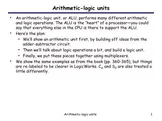
Abstract • Our team successfully designed an 8-bit ALU using two 4-bit CLA stages. • ALU performs 8 arithmetic operations and 4 logic functions. • Designed circuit was simulated and verified in schematic and layout. • We used the AMI06 process technology in our design. • Design meets 200 MHz operation speed specification. • Circuit power consumption is 29.9 mW and has an area of 474.2 μm x 368.7 μm.
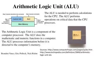
Introduction • We chose the Arithmetic Logic Unit as our design project because of its importance to the execution unit of a computer’s CPU. • Our 8-bit ALU design is based on the 74LS181 component. • Arithmetic/Logic Operation controlled by four input lines: S1, S2, M, and Cn. • Our specification is to design for an operation speed of 200 MHz or faster.
Project Details:8-Bit ALU Logic Schematic Logic gate schematic of 8-bit ALU showing input/outputs.
ALU Functions/Operations ALU performs four logic functions and eight arithmetic operations depending on the inputs: S3, S1, M, and Cn.
NC-Verilog Simulation NC-Verilog output simulation is shown for 4-bit case for easier waveform readability.
Worst-Case Vector & Path A3 set high and B3 toggled to produce a carry-out from the first 4-bit stage into the second.
Hand Calculations for Size & Delay • Above are the design equations used in our hand calculations. • We used a spreadsheet for quick accurate calculations.
Transistor Sizes & Delay Times Our design goal was minimum width with symmetric propagation time.
D Flip-Flop Size & Delay Time • Table of transistor sizes used in our Mux-Based DFF. • Design goal was to allocate 1 ns to the DFF.
8-Bit ALU Layout The overall layout of our ALU circuit using the AMI06 process.
A7, B7 F7 A6, B6 F6 A5, B5 F5 A4, B4 F4 A3, B3 F3 A2, B2 F2 A1, B1 F1 A0, B0 F0 C8 S3 S1 C0 M ALU Block Layout The ALU layout with the cell outlines shown.
DRC & Extraction Results • Layout successfully passes DRC. • Parasitic capacitances are extracted that will be used to compare • if layout and schematic are electrically equivalent.
LVS Output file confirms LVS check is successful!
Simulation Results Simulation results for various test vectors.
Worst-Case SPICE Simulation Worst-case delay of analog_extracted circuit: 3.98 ns
Results • 8-bit ALU performs eight arithmetic operations and four logic operations • Operation speed: 200 MHz • Worst-Case Delay: 3.98 ns • Power: 29.9 mW • Area: 474.2 μm x 368.7 μm
Cost Analysis: Project Design Time Total project from start to finish was approximately 5 weeks.
Lessons Learned • Very Important Lesson: Time Management • How to achieve symmetric propagation. • Knowing where to use buffers. • Paying attention to fan-in and fan-out. • Using cell-based design simplifies layout.
Conclusions • The Arithmetic Logic Unit is an important part of computer CPU’s. We learned how to produce different arithmetic operations and logic functions by using various select singles for a single circuit. • Actual operation speed of designed ALU is faster than specification. • Low power consumption and small area. • Designed ALU was 8-bit, four bits more than previous projects. • Preparation of an overall stick diagram of the entire circuit allowed quick, efficient organization of our layout. • Great teamwork helped us achieve our project goal!
Acknowledgements • Thanks to Dr. David Parent for providing project guidance and very helpful tutorials. • Thanks to Cadence Design Systems for the VLSI lab. • Thanks to our families for putting up with us. • Thanks to our colleagues in the lab.