Download
1 / 8
80 likes | 300 Views
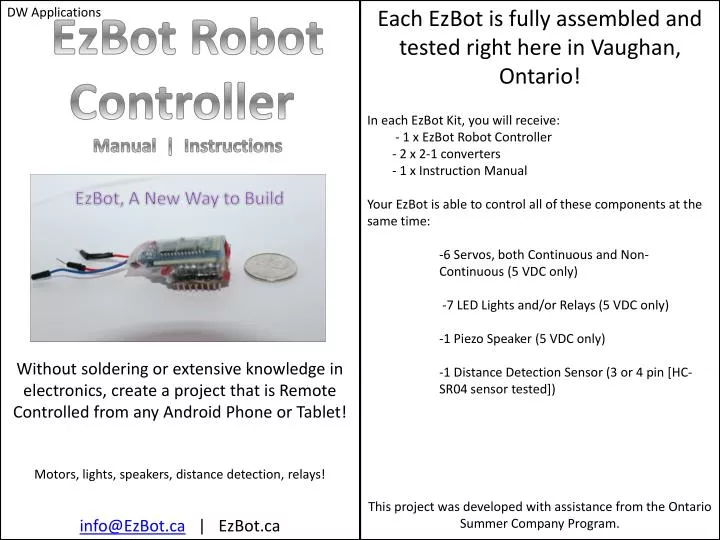
E. DW Applications. EzBot Robot Controller Manual | Instructions. E. Each EzBot is fully assembled and tested right here in Vaughan, Ontario! In each EzBot Kit, you will receive: - 1 x EzBot Robot Controller - 2 x 2-1 converters - 1 x Instruction Manual

E N D
E DW Applications EzBot Robot Controller Manual | Instructions E Each EzBot is fully assembled and tested right here in Vaughan, Ontario! In each EzBot Kit, you will receive: - 1 x EzBot Robot Controller - 2 x 2-1 converters - 1 x Instruction Manual Your EzBot is able to control all of these components at the same time: -6 Servos, both Continuous and Non- Continuous (5 VDC only) -7 LED Lights and/or Relays (5 VDC only) -1 Piezo Speaker (5 VDC only) -1 Distance Detection Sensor (3 or 4 pin [HC- SR04 sensor tested]) This project was developed with assistance from the Ontario Summer Company Program. Without soldering or extensive knowledge in electronics, create a project that is Remote Controlled from any Android Phone or Tablet! Motors, lights, speakers, distance detection, relays! info@EzBot.ca | EzBot.ca
The EzBot; Power Powering your EzBot: The EzBot was developed with efficient power use in mind! Each EzBot has 5 wires coming out which will be used to power it to allow you to create a long-lasting project. Red: + 5V-6V power source. Powers the EzBot Robot Controller, Relays, LED, Ping Sensor and Piezo Speaker. This allows for 100% efficiency. Yellow: + 6.5V-12V power source. Powers the EzBot Robot Controller, Relays, LED, Ping Sensor and Piezo Speaker. This reduces efficiency due to voltage regulation. • DO NOT PROVIDE POWER TO BOTH YELLOW AND RED WIRE AT THE . SAME TIME. DO NOT PROVIDE MORE POWER THEN MENTIONED, THIS MAY CAUSE PERMANANTE DAMAGE TO THE EZBOT. IT IS RECOMMENDED TO FIRST POWER THE EZBOT FROM THE YELLOW WIRE AND IF THE EZBOT CONSTANTLY RESETS OR DOES NOT LIGHT UP, ATTEMPT TO POWER FROM RED WIRE TO AVOID DAMAGE. Black: Used as ground for the EzBot Robot Controller, Relays, LED, Ping Sensor and Piezo Speaker. Green: + for Servos only. Provide power depending on the servo type. Most Servos that are compatible with the EzBot work with 5V-7.2V. Blue: - for Servos only. Used as ground for Servos only. (Not required is Servos will be working from the same power source as EzBot.) • Powering the EzBot: • There are 3 main methods in powering the EzBot and its components. • 1) Single Power Source of 5V-6V. Use the 2-to-1 converter to attach both the green wire and the red wire to the positive of the power source. Attach the black wire to the negative of the battery source. • 2) Single Power Source of 6.5V-12V. Use the 2-to-1 converter to attach both the green and the yellow wire to the positive of the power source. Attach the black wire to the negative of the battery source. NOTE THAT MANY SERVOS ARE ONLY ABLE TO WORK WITH UP TO 7.2V. ANYTHING OVER THAT CAN DAMAGE THE SERVO. E 3)2 Power Sources, 1 for Servo, 1 for EzBot and all other components. In this scenario, you can control Servos from a different power source then the EzBot and the rest of the components. Select one power source to power the EzBot. If the power source is between 5V-6V, connect the red wire to the positive of the first source. If the power source is 6.5V-12V, connect the yellow wire to the positive of the first source. Connect the black wire to the negative of the first power source. Your EzBot should start working now. Your second source, the one which will power the servos, should be between 5V-7.2V. Connect the green wire to the positive of the second power source and the blue wire to the negative of the second source. This will provide current to your Servos. Illustration for method 1 (Only necessary wires are shown) Red EzBot Green 2-to-1 Converter Black 5V-6V • Illustration for method 2 (Only necessary wires are shown) Yellow EzBot Green 2-to-1 Converter Black 6.5-12V • Illustration for method 3 (Only necessary wires are shown) Red if source is 5-6V, Yellow if source is 6.5-12 V EzBot Black 5-12V (source 1) Blue 5-7.2V (Source 2) Green
The EzBot; Connecting Components • The EzBot is able to control up to 6 Servos, 7 LEDs or Relays, 1 Ping Distance Detection Sensor and 1 Piezo Speaker. The EzBot has 3 rows of pins on either side. The 2 sets of inner pins are signal pins. All of your components will be connected to at least one of these signal pins as that is how the EzBot will control them. The 2 sets of pins in the middle are + power. The 2 sets of outer pins are - (ground). You can refer to illustration 4 for clarification. Servo: The Servo is the life of your project, it can make your project move around and explore its environment. A Servo has 4 major parts: • Normal DC motor • Gear reduction • Volume control knob • Control circuit. • There are 2 main servos that are compatible with the EzBot, Non-Continuous • and Continuous Servos. Non-Continuous Servos move only 180 degrees while • Continuous Servos move 360 degrees without restriction. • Connecting your Servo to the EzBot: • Each Servo has 3 wires. Usually colour coded [White, Red, Black] or [Yellow, • Red, Brown]. In both cases, the lightest colour (white/yellow) is the signal • pin, red is the positive and the darkest colour (back/brown) is negative. • Referring to the illustration number 4 (picturing the EzBot) and the • illustration number 2 (picturing the servo wires), you can see that the female • Socket (illustration 2) is able to simply plug into EzBot pins. It would be • plugged in so that the black wire matches up with Negative pin, the red wire • matches up with the Positive pin and the White wire matches up with the • Signal pin. You can connect a servo on each column labelled 1-6. E E • Ping Distance Detection Sensor: • This sensor, also called the Ultrasonic Sensor or “Ping”, • sends a brief ‘chirp’ with its ultrasonic speaker and • then picks the sound up with its ultrasonic microphone. • The EzBot is able to determine how long it takes for the • sound to hit something and go back to the sensor, • which it uses to find the distance. • Connecting your Ping Distance Detection Sensor to the EzBot: • The most common Distance Detection Sensor has 4 pins named VCC, Trig, • Echo, and Gnd (these can be found on the sensor). Connect the Trig pin to • Signal Pin 7, the Echo pin to Signal Pin 8, the VCC pin to the + pin located on • the same column as the Signal Ping 7, the Gnd pin to the - pin located on the • same column as the Signal Pin 7. You will have to use female-to-female wires • for these four connections. • LED: • LEDs, also called Light Emitting Diodes, are small lights that do not emit heat • and only allow current to flow one way. • Connecting your LEDs to the EzBot: • In all LED’s compatible with the EzBot, there is a long pin for • positive and short pin for negative (illustration 3). Connect the • long pin to the Signal Pin and the short pin to the - Pin on the same column • as the signal pin. An LED can be connected on a pin from column from 10-16. • You will have to use female-to-female wires for each connection. (3) (4) Use this illustration as a reference. Place your EzBot in the position shown below. e.g. Column 10 - Pin row + Pin row Pins Signal Pin row (2) Power Wires Bottom Sticker # of column Signal Pin row + Pin row Pins - Pin row
Relays: • A relay is a device which is commonly used to power larger devices from a smaller current. It acts as a switch which completes a circuit whenever a signal is sent to it. With this, you can power DC motors, larger lights and many other peripherals. • Connecting your Relay to the EzBot: • Many have multiple pins, however, only 3 are required to use them with the • EzBot. These pins are • Power pin. Called VCC, VIN, or + • Ground pin. Called Gnd or – • Signal pin. Called IN1 or S. May have other names. • Connect the Signal Pin of the Relay to any signal pin of the EzBot from • column 10-16 (illustration 4). Connect the Relay’s power pin to the + pin on • the EzBot on the same column as the signal pin. Connect the ground pin of • the Relay to the - Pin on the EzBot in the same column as the signal pin. You • will need to use female-to-female wires for this connection. • Using the Relay in a simple circuit • In order to use the Relay as a switch for the component it is controlling, • create a simple open circuit (illustration 5). Connect one side of the open • circuit to the central knob of the relay, you can use the embedded screw to • tighten the wire attached. A relay has 2 states, normally off and normally on. • If you attach the second wire of the simple circuit to normally on, it will • complete the circuit with the relay is turned off and not working. If you • attach the second wire of the simple circuit to normally off, it will compete • the circuit Only when you turn on the relay. There are many different relays • so you may have to experiment if the peg to the left/right is normally on/off • and which one fits your purpose. E E • Piezo Speaker: • A Piezo Speaker is a small speaker which is able to play • Tones at different frequencies by varying the Hertz • that it vibrates/oscillates at. • Connecting your Piezo to the EzBot: • A Piezo has 2 pins coming out, one is the positive + pin and • the other is the ground - pin. The positive pin is identified by a small + sign on • the top of the Piezo speaker. Connect the positive pin of the Piezo Speaker to • the Signal pin at column 9 on the EzBot. Connect the ground pin of the • Piezo to the - pin of the EzBot at column 9. You will have to use female-to- • female wires for this connection. Illustration of where to connect components to the EzBot LED’s long pin connected to Signal pin, LED’s short pin connected to - pin. Relays S or In1 pin connected to signal pin, Relay’s VCC pin connected to + pin, Relay’s Gnd pin connected to – pin. (10-16) Piezo Speaker, + of speaker to signal pin, - of speaker to - pin of EzBot. (9) - Pin row + Pin row Pins Signal Pin row Power Wires Bottom Sticker # of column Signal Pin row (5) Simple Circuit + Pin row Pins - Pin row Servo’s White/Yellow wire connected to Signal pin, Red wire connected to + pin, Black/Brown wire connected to - pin. (1-6) Ping Sensor’s Trig pin connected to Signal pin 7, Ping Sensor’s Echo pin connected to Signal pin 7, VCC pin connected to + pin in column 7, Gnd pin connected to - pin in column 7. (7-8) Can be light, DC motor, etc The Relay will act as the switch
E The App • Downloading and Installing: • You must first install the EzBot app on your device which is • found on Google Play. It goes by the name of “EzBot Robot • Controller” (no quotations) with DW Applications as the • Developer. • Connecting your phone to the EzBot: • Press the “Connect to EzBot” (no quotations) button on the menu of the EzBot app. You will be guided through the connection process by checkmarks or incomplete signs. If you encounter an incomplete sign after multiple attempts at a connection, please check troubleshooting. • Password: • If this is your first time connecting to a specific EzBot, you will be required to input a password. Please input the password “1234” (no quotations) to complete the connection process. You will not be asked to do this again. • Creating a Layout: • Press the “+ New Layout” button on the main menu to make a layout. Here you have tools available to make your layout. Use the “+” button to add a new item, use the undo button to remove the previously added item and use the “x” button to remove a specific item. Press “Background” to change the background. Press “Finished” to name and test your layout. • Adding a new item to your layout: • Press the “+” button. Select the type of item you want to add (button, checkbox, etc). Use the “Color”, “Text Color”, “Text” and the “Size” seek-bar to edit the item that you will add. • Press the “Function” button to give a purpose to the item you are about to add. On the left side, you will have a list of the different functions that you can give to an item. Each number directly correlates to the EzBot pin labels located on the bottom of the EzBot. Refer to “Editing the item” illustration. • Refer to “Main Menu of the App” illustration for more detail. E Main Menu of the App Start the Connection Process Connection Process Load an existing layout Make a new layout Editing the item Select what the item should be Decide what the item will do Preview Add the item to the layout
E • Editing components on your layout: • Adding a Servo (to the layout): • Click the Servo with the number (referencing the pin) that you would like to control. • -Select if your Servo is Continuous or Non-Continuous. This is not a preference. You MUST select the correct option for the servo to work properly. They can be distinguished using this method: • 1. Attach a horn/grip the part of the Servo that rotates • 2. Turn the motor slowly • 3. If the Servo allows you to turn to a certain point, it is Non-Continuous. If you are able to turn the Servo a full 360 degree without stop, it is Continuous. • -Select the direction you would like the Servo to turn • -Select the speed. Using the Speed 0/12 is useful for when the motor must hold its position. An example may be a robotic arm which should stay in its position. • -Press the “Test” button if you are connected to the EzBot to ensure the motor works as required. This function only works if you are connected to an EzBot. • Adding an LED/Relay (to the layout): • -Click the LED/Rel with the number (referencing the pin) that you would like to control. This would mean the LED or Relay you are trying to control would be connected to that same pin number. • -Press the “TEST” button to ensure that the LED or Relay works as required. This function only works if you are connected to an EzBot. • Adding a Piezo Speaker (to the layout): • -Click the Piezo button. A Piezo must be connected to the allotted Piezo pin on the Ezbot (pin 10). • -Select the amount of Hz you would like the Piezo to output. The Piezo output is limited to a Hertz of 4 digits with no decimals (0-9999). • -Press the “Test” button to ensure that the Piezo works as expected. This function only works if you are connected to an EzBot. • Adding a Ping Sensor (to the layout): • -Click the Ping Sensor button. A Ping Sensor must be connected to the allotted Ping pins on the EzBot (Pin 9 and 10). • -Press the “Test” button to receive the distance the Ping Sensor detects. E • If you receive a measurement of “0” with nothing in front of Sensor or do not receive any measurement, check the troubleshooting section. This function only works if you are connected to an EzBot. • Placing items on your layout: • Move the item to the location you want it. Press the checkmark when satisfied with the location. Continue the process in this section until you have a completed layout. • Testing a Layout: • Once you are finished creating you will have the opportunity to test it and ensure everything works. This will only be available if you are connected to an EzBot.If you are not satisfied with how one or more of the items on your layout works, press the back button to continue editing. If you are satisfied, press the “Finished Testing” button. • Running an Existing Layout: • Click the name of the layout you want to run. Your layouts are located in the main menu under “Run a layout” heading. Deciding the function Finish editing function Edit the settings Test how the settings work Decide what to control
Troubleshooting • EzBot Connection Problem (incomplete signs, EzBot not responding to command): • -Cannot connect for the first time use => • 1)Go to Settings>Bluetooth on your device, search devices, find HC-06 device, pair, input password 1234. • 2) If still not connected, attempt to unpair a few of your • existing Bluetooth devices • -Receiving fail sign under “Starting Connection Process” => • 1) Restart your Android • -Receiving fail sign under “Finding Bluetooth Device” => • 1) Ensure EzBot has small red, blinking light on top. If solid • light, unplug and replug the EzBot to power source. If no light, check the connection to the power source. • 2)Restart the app • -Receiving fail sign under “Attempting to Connect” => • 1) Ensure EzBot has small red, blinking light on top. If solid • light, unplug and replug the EzBot to power source. If no light, check the connection to the power source. • 2) Restart the app • -EzBot not responding to commands or testing => • 1) Ensure the EzBot has solid red light on top. If blinking, • restart the app and reconnect. If off, check EzBot’s • connection to power source. • 2) Restart the app • -Not Receiving Ping Sensor feedback from the EzBot • 1) Restart the Android App • 2)Press EzBot’s reset button • Problems with components • -Sevo moving in unexpected way => • 1) Ensure that you have selected the correct option for if it is • Continuous or Non-Continuous • 2) Calibrate servo if possible • 3) Ensure that you are providing between 5V-7.2V • 4) If Non-Continuous servo, it may just be alignment; normal • -Servo making sounds, not moving => • 1) Check wiring • 2) Increase the speed • -Servo not moving => • 1) Check wiring E E 2) Ensure you are powering the EzBot correctly. The green wire must be connected to the positive of the power source, this if the power source for Servos 3) Check to see if another Servo works, it may be fried 4) Make sure you connected it to the correct pin you are testing with. -LED not working => 1) Ensure correct wiring, LEDs only light up if current goes into the correct pin. 2) Check another LED, it may be fried 3) Ensure its connected to the pin your are testing with -Relay not turning on => 1) Ensure wiring is correct. 2) Check another relay, it may be fried 3) Ensure its connected to pin you are testing with -Relay not turning on separate simple circuit => 1)Ensure that relay is the only open switch in the circuit 2) Use another relay, it may be fried 3) Ensure the wiring is correct -Piezo not turning on => 1)Ensure that the Piezo is wired correctly (only pin 10) 2) Use another Piezo, it may be fried 3) Ensure you are sending Hz between 1-9999 -Ping Sensor bringing back “0” only => 1) Check wiring, this is usually the main reason(pin 8,9) 2) Test with another Ping Sensor, it may be fried 3) Provide at least 10cm of clearance from the closest object -Ping Sensor bringing back very large number over 3000 => 1) Make sure there is an object closer then 4 meters 2) Try changing the power source/replacing batteries 3) Make sure that there is nothing closer then 10 cm EzBot constantly Restarts (evident by blue light constantly flickering) -Check the power source, it may not be enough. If powering with yellow wire, change to red wire -Check wiring of components, ensure there are not short circuits forming Contact us at info@ezbot.ca if you are still experiencing problems.