Download
1 / 14
170 likes | 448 Views
Unit 8 Controller Design of Mobile Robot. 中華技術學院電子系 講師 蔡樸生. Structure of Mobile Robots. Mobile Robot Posture. Define Posture Vector Rotation Matrix Inertial / Body Frame. Attitude. The Conception of Controller. Plant. +. Controller. Driver. -. Mobile Robot. Sensor. Encoder.

E N D
Unit 8 Controller Design of Mobile Robot 中華技術學院電子系 講師 蔡樸生
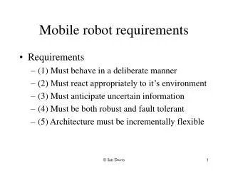
Mobile Robot Posture • Define Posture Vector • Rotation Matrix • Inertial / Body Frame Attitude
The Conception of Controller Plant + Controller Driver - Mobile Robot Sensor Encoder • Enhance the performance of the origin system • Eliminating the steady state error • Reducing the overshoot of the system
The Kinematics of Mobile Robot • The kinematic Model • Error Posture Configuration (Plant)
The Derive of Error Equation • Taking the change of inputs • Error Equation where
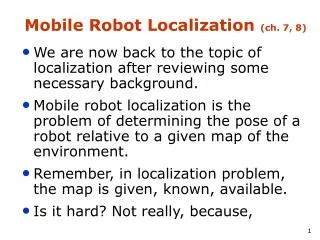
The purpose of Controller Design • The problem we consider here is the tracking problem. A control input is attempted to the posture error trajectories converge to zero, i.e., Reference linear Velocity Reference angular Velocity
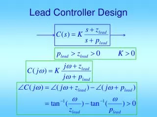
Lyapunov Synthesis Controller Design Backstepping Procedure Controller Design
Flow Chart of Program Start Calculate Response Trajectory Tracking Calculate Controller Design
Calculate % 圓形 xr(k)=R1*sin(w*dt*k); yr(k)=R1*(1-cos(w*dt*k)); % S型曲線 xr(k)=R2*(sin(w*dt*k)^2-0.5); yr(k)=R1*(1-2*(cos(2*w*dt*k))*(sin(2*w*dt*k))); % 四尖擺線 xr(k)=R1*(cos(w*dt*k)^3); yr(k)=R1*(1-(sin(w*dt*k)^3)); % 螺旋線 xr(k)=R3*cos(w*dt*k)+R3*(w*dt*k)*sin(w*dt*k); yr(k)=R3*sin(w*dt*k)-R3*(w*dt*k)*cos(w*dt*k)+10;
Calculate dxr(k)=(xr(k)-xr(k-1))/dt;dyr(k)=(yr(k)-yr(k-1))/dt; vr(k)=sqrt(dxr(k)^2+dyr(k)^2); sitar(k)=atan2((dyr(k)/vr(k)),(dxr(k)/vr(k))); wr(k)=(sitar(k)-sitar(k-1))/dt; Calculate Pr=[xr(k);yr(k);sitar(k)];Pc=[xc(k);yc(k);sitac(k)]; wr(k)=(sitar(k)-sitar(k-1))/dt;T=[cos(sitac(k)) sin(sitac(k)) 0; -sin(sitac(k)) cos(sitac(k)) 0;0 0 1]; Pe=T*(Pr-Pc); xe(k)=Pe(1,1);ye(k)=Pe(2,1);sitae(k)=Pe(3,1);
Control Design vc(k)=vr(k)*cos(sitae(k))+k1*xe(k); wc(k)=wr(k)+k2*vr(k)*ye(k)+k3*vr(k)*sin(sitae(k)); System Model xc(k+1)=vc(k)*cos(sitac(k))*dt+xc(k); yc(k+1)=vc(k)*sin(sitac(k))*dt+yc(k); sitac(k+1)=wc(k)*dt+sitac(k); Plot X-Y Trajectory
Remarks • For k=2:step • k1=3,k2=2,k3=1 • step=4000;dt=0.002; • initial value : • for k=1:(step/50) • [h1,h2,h3,h4,h5,h6]=create_robot(x(50*k),y( 50*k),sita(50*k)); • pause(0.5); • end