Download
1 / 29
300 likes | 488 Views
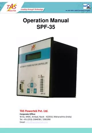
Operations Manual SPF-25/6 AUTOMATIC POWER FACTOR CONTROLLER. TAS Powertek Pvt. Ltd. Corporate Office: W-61, MIDC, Ambad, Nasik - 422010, Maharashtra (India) Tel: +91-(253)-2384038 / 2381090 Email: sales@taspowertek.com. NOTE

E N D
Operations Manual SPF-25/6 AUTOMATIC POWER FACTOR CONTROLLER TAS Powertek Pvt. Ltd.Corporate Office: W-61, MIDC, Ambad, Nasik - 422010, Maharashtra (India)Tel: +91-(253)-2384038 / 2381090Email: sales@taspowertek.com
NOTE These instructions do not purport to cover all details or variations in equipment, nor to provide for every possible contingency to be met in connection with installation, operation or maintenance. Should further information be desired or should particular problems arise which are not covered sufficiently for the purchasers purposes, the matter should be referred to our TAS Powertek Pvt. Ltd., office. The contents of this instruction Manual shall not become part of or modify any prior or existing agreement or relationship. The sales contract contains the entire obligations of TAS Powertek Pvt. Ltd. The warranty contained in the contract between the parties is the sole warranty of TAS Powertek Pvt. Ltd. Any statements contained herein do not create new warranties or modify the existing warranty. The reproduction, transmission or use of this document or its contents is not permitted without express written authority. Offenders will be liable for damages. All rights are reserved.
Index Index Page ------------------ 1 Features & Specifications ----------- 2 Mechanical Dimensions/ mounting --------- 3 Functional Block diagram ------------------ 4 PF correction technique ------------------ 5 Back Side terminals ------------------------ 6 Typical wiring scheme ---------------------- 7 Front Facia ---------------------------------- 8 Communication connector connections ----- 9 Display of various parameters / Status ---- 10 Method of Keyboard/Display usage -------- 19 Parameter Submenu ------------------------ 22 Commissioning Instruction (before Powerup) 24 Fault finding Guidelines --------------------- 25 - 1 -
Features: • Totally Micro-processor controlled Digital Signal processing • logic for measurements. • All measurements with 1.0 class accuracy. • Automatic Synchronisation capable of giving the correct • results for wrong connections at CT terminals (even wrong • polarity of CTs). • Measurement and kVAr compensation are frequency / THD • compensated. • Load V,Iph, In and Cap. current THD measurement. • Up-to 6 output banks control. • Capable of doing the kVAr measurements on basis of mean • of the correction cycle time and provide kVAr compensation. • Standard 144 X 144 cabinet for panel door flush mounting. • Serial communication through standard TAS protocols. • Manual testing mode for user checking of the Capacitor steps • switching. • Protections provided (user settable): • Over/under Voltage • Cap. Over/under current / THD. • Over/Under frequency (internally set limits) • Over / Under load. • Load unbalance. • Capacitor individual step kVAr monitoring. • Out of steps: Under-compensation (only for indication) • NV-RAM battery down. • Data logging for various parameters for 2months period at an • interval of 1hr. • Unit comes along with PC (Windows compatible) software • for downloading and viewing the logged data. • Specifications: • Feed-back Voltage:440Volt (+10%/-30%) • Current input : 1Amp for load and capacitor feed-back. • Measurement Accuracy: Class 1.0 • Auxiliary Supply: 525Vac to 300Vac. • Correction / Discharge time: • Selectable in seconds from 10sec. to 240sec. • Output commands: • NO contacts each with current rating of 0.5Amp AC. at • 240Vac. • RS-232 baud rate selectable from 4.8kBPS to 38.4kBPS. • Operating temperature: 0 to 55oC. • 1.0class measurement Operating temperature: 0 to 50oC. • Storage temperature: -10 to +75oC. • Humidity: 0 to 98%. • Supply frequency: 45Hz to 55Hz. - 2 -
135 144 135 120 144 6 Mechanical Dimensions: Recommended size for cutout on panel door is 138 X 138. All Dimensions given are in mm. Maximum weight: (with clamps and terminals) = 2.5kg. - 3 -
3 channel Current f.b. 3 channel Voltage f.b. EEPROM For Data Logging SPF-25 V, I, PF and Power Measurement Block For every AC mains Cycle. 3 Channel Cap. Current f.b. RS-232 Serial Communication. TAS-01 Protocol stack. Keyboard, Display and Other support Functions Block. • Calculation • Block for • Energy Parameters • Harmonic analysis Power Factor Correction Block + event monitoring. Outputs Commands For Capacitor Switching. Power Supply Block. Functional Block Diagram: Above block diagram gives the functional blocks that are built into SPF-25 PF correction relay. These blocks are made up with the combination of functions from hardware and corresponding firmware that resides in the Program memory of the micro-processor used therein. Even though the basic blocks exists as shown in the diagram, there functionality is interdependent. The entire combination is carefully designed so as to have minimum effects of Electrical and Electromagnetic noise level on the functionality of this SPF-25. The firmware written takes into various error handling eventualities so that the functioning of this PF relay is error free and highly reliable. - 4 -
KVAr Inductive Cos Φ = PF Target PF. 1.5 X kVAr Of Smallest Capacitor bank No change band. Capacitor Addition band. Capacitor Removal band. KW KVAr Capacitive PF correction technique: SPF-25 for kVAr compensation works with the kW v/s kVAr diagram as shown here above. A band is created across the target PF value. (Target PF is set by user). This band is of +0.75 of the smallest capacitor bank kVAr. Thus, total band width is always 1.5 times the smallest capacitor bank kVAr used. This is a no change band. If the mains source parameters are within this band, SPF-25 would not change the capacitors bank status. If the mains parameters are out of this “No change band”, then SPF-25 calculates the correct capacitor bank combination to be added / subtracted and within one correction cycle brings it within the No change band. The no change band width is selected as mentioned because it has to prevent un-necessary hunting (switching on/off) of the capacitor banks. - 5 -
Voltage Feed-Back Auxiliary Supply Current Feed-Back Capacitor Current Feed-Back Output commands. Back Side terminals: - 6 -
L L L L L L C C C C C C R R Y Y B B + - + - + - CCR+ CCR- CCY+ CCY- CCB+ CCB- L1 L2 Mains Connections: Phase 1 control: Neutral control: Commands: Load Current CT: Capacitor Current CT: Typical Wiring with SPF-25 PF correction system. L O A D PH 3 PH 2 PH 1 Auxiliary Supply S P F - 2 5 Com C01 C02 | C06 - 7 -
Front Facia of SPF-25: LCD Display Step status LED indication Serial Communication Port Membrane Keypad Usage of the UP and DN key makes the LCD display to scroll up and down. This is used for display of various status as well as for viewing the On line measured electrical values. These keys are also used for changing values in Parameters Editing mode and used for status changing of banks in Manual mode. Usage of ENT key is for entering the submenu and / or for setting up some values. The L and R keys are used in changing the position of the cursor from Left to Right and vice-versa. - 8 -
5 4 3 2 1 6 7 8 9 RXD GND TXD RS-232 serial communication 9 pin D connector: RS-232 cable connection Details: - 9 -
COSΦ= -0.99 A OK Display of Various Parameters / Status: PAGE: 00 This is default display screen giving information on PF, mode and working status. COSΦ= -0.99 :This part of the display indicates the Power Factor running value. The sign –ve indicates that PF is Capacitive and no sign (+ve) indicates that PF is Inductive. The PF indicated is the overall PF of the three phase system. A or M : This part either indicates the letter “A” or letter “M”. The letter A means that SPF-25 is working in Auto mode. The letter M means that SPF-25 is presently in Manual mode. The Auto or Manual modes can be selected by pressing ENT key on this page. (If Password option is enabled, enter the same by using UP/DN/L/R keys and then Pressing ENT) Then by UP or DN key you can stroll between the displays: “1. Edit Mode”, “2. Auto Mode”, “3.Manual Mode”. The first one “1.Edit Mode” is for parameter changing. The details of parameter changing are explained in detail in later part of this manual. The second and third one as display indicates are for selecting Auto or Manual mode respectively. The ENT key pressed on selecting the mode desired, puts the SPF-25 into that mode. Auto Mode: In this mode SPF-25 works in automatic mode. It switches the capacitor banks automatically depending on the parameter setting of target PF. This mode is the default mode and is to be used for unmanned operation of the system controlled by SPF-25. Manual Mode: This mode is activated for checking/testing the capacitor banks switching. Its also used for changing the Masking status of the capacitor banks. More on this is explained later. (On Page 01 explanation) OK or ** : The last part of the display that is blinking every 500mS indicates the working status of SPF-25. “OK” indicates that unit is working fine without any trip conditions. If there is other indication, the meaning of the same can be as: OK : No Fault OC : Over Capacitor Current UC : Under Capacitor Current OL : Over Load UL : Under Load OV : Over Voltage UV : Under Voltage OF : Over Frequency UF : Under Frequency OH : Over Capacitor Current THD %. OB : Out of Banks LU : Load Unbalance BF : Battery Failure (RTC) NV : NVRAM Checksum Error VA : Voltage Absent - 10 -
PAGE: 01 PAGE: 01 ______ AUTO ______ MAN This display indicates the Bank status in Auto mode and in Manual mode it helps to make the specific bank On or Off or declare masked. : Means Bank is On. : Means Bank is Off. : Means Bank is Off and is declared masked (out of action) : Means Bank does not exist for compensation. When the Page 01 is in Auto mode, its only for indication of Bank status. But in Manual mode, the “ENT” key press activates the manual control mode. The cursor over the bank number starts blinking. The UP and DN keys can turn On and Off the respective bank. The DN key pressed puts the respective bank in Masking mode and another press of DN key brings it out of Masking mode. Putting the bank masking status permanently: If a bank is to be permanently put in masked mode or is to be brought out of permanent masked mode, it can be done by bringing the blinking cursor on the position of the respective bank by use of L or R key. Then by pressing DN key, bring the status of the bank to the required level (Masked or Unmasked). Then press ENT key so that cursor stops blinking. After that by pressing UP key go to Page 00. Then Press ENT. (If Password option is enabled, enter the same by using UP/DN/L/R keys and then Press ENT) “1.EDIT MODE” would be displayed. Press ENT one more time. “1.General and IO” would be displayed. Press ENT again. “Pwd : Disable” or “Pwd : Enable” would be displayed. Press UP key. “Exit: No Save” would be displayed. Press ENT so that cursor will start blinking. Press UP. “Exit: With Save” would be displayed with cursor blinking. Press ENT. “Saving in EEPROM” would be displayed for a short time and then Page 00 would be displayed. You will observe that the bank status as requirement is changed permanently to the status desired. - 11 -
PAGE: 02 1.Overall Values PAGE: 02.1 Avg Vol: 415.7 V PAGE: 02.2 Avg Cur: 0123.4A PAGE: 02.3 Tot KW: 0081.2 PAGE: 02.4 TotKVAR: 0024.6 PAGE: 02.5 Tot KVA: 0101.1 PAGE: 02.6 Avg CC: 0031.3A PAGE: 02.7 CKVAR: 028.35 PAGE: 02.8 LS PF: 0.82 PRESS PAGE: 02.9 LS KVAR: 0043.9 PAGE: 02.10 LS KVA: 0125.7 PAGE: 02.11 Freq: 49.9Hz The Overall values Display menu has submenus as displayed above. As its self explanatory it means: Avg Vol: Average voltage of all the three line to line voltage values. Avg Cur: Average current of all the three phase line current values. Tot KW: Overall kW of the three phase system measured at source. TotKVAR: Overall kVAr of the three phase system measured at source. Tot KVA: Overall kVA of the three phase system measured at source. Avg CC: Average of three phase current through capacitor panel. CKVAR: Capacitive kVAr that is compensated by the system. LS PF: Load side PF. (PF value if not compensated. LS KVAR: Load side kVAr. LS KVA: Load side kVA. Freq: Supply frequency in Hz. - 12 -
PAGE: 03 2.Per-Phase RMS PAGE: 03.1 R-Y Vol: 415.7 V PAGE: 03.2 Y-B Vol: 415.7 V PAGE: 03.3 B-R Vol: 415.7 V PAGE: 03.4 Rph Cur: 0110.8A PAGE: 03.5 Yph Cur: 0110.8A PAGE: 03.6 Bph Cur: 0110.8A PAGE: 03.7 Neutral: 0010.2A PAGE: 03.8 Rph Cap: 0022.5A PRESS PAGE: 03.9 Yph Cap: 0022.5A PAGE: 03.10 Bph Cap: 0022.5A Per Phase RMS: Submenu: R-Y Vol: Measured AC Voltage RMS value across R and Y phase. Y-B Vol: Measured AC Voltage RMS value across Y and B phase. B-R Vol: Measured AC Voltage RMS value across B and R phase. Rph Cur: Line current RMS value in R phase. Mains source. Yph Cur: Line current RMS value in Y phase. Mains source. Bph Cur: Line current RMS value in B phase. Mains source. Neutral: Neutral current RMS value. Rph Cap: Capacitor current RMS value in R phase. Yph Cap: Capacitor current RMS value in Y phase. Bph Cap: Capacitor current RMS value in B phase. - 13 -
PAGE: 04 3.Power PRESS PAGE: 04.1 PAGE: 04.10 Rph PF: 1.00 Rph KVA: 0109.7 PAGE: 04.2 PAGE: 04.11 Yph PF: 1.00 Yph KVA: 0109.7 PAGE: 04.3 PAGE: 04.12 Bph PF: 1.00 Bph KVA: 0109.7 PAGE: 04.4 PAGE: 04.13 Rph KW: 0100.2 RphCKVAR: 010.76 PAGE: 04.5 PAGE: 04.14 Yph KW: 0100.2 YphCKVAR: 010.76 PAGE: 04.6 PAGE: 04.15 Bph KW: 0100.2 BphCKVAR: 010.76 PAGE: 04.7 PAGE: 04.16 RphKVAR: 0020.4 Rph mF : 165.06 PAGE: 04.8 PAGE: 04.17 YphKVAR: 0020.4 Yph mF : 165.06 PAGE: 04.9 PAGE: 04.18 BphKVAR: 0020.4 Bph mF : 165.06 Power: Submenu: Rph PF: Power Factor of R phase on mains source. Yph PF: Power Factor of Y phase on mains source. Bph PF: Power Factor of B phase on mains source. Rph kW: Active Power in kW in R-phase. Yph kW: Active Power in kW in Y-phase. Bph kW: Active Power in kW in B-phase. RphkVAR: Reactive Power in kVAr in R-phase. YphkVAR: Reactive Power in kVAr in Y-phase. BphkVAR: Reactive Power in kVAr in B-phase. Rph KVA: Apparent Power in kVA in R-phase. Yph KVA: Apparent Power in kVA in Y-phase. Bph KVA: Apparent Power in kVA in B-phase. RphCKVAR: Capacitor injected reactive power in R-phase. YphCKVAR: Capacitor injected reactive power in Y-phase. BphCKVAR: Capacitor injected reactive power in B-phase. Rph mF: Capacitor value in micro-farad in R-phase. Yph mF: Capacitor value in micro-farad in Y-phase. Bph mF: Capacitor value in micro-farad in B-phase. - 14 -
PAGE: 05 4.Energy PAGE: 05.1 KWH: 1234567.8 PAGE: 05.2 IndKVARH:12345.6 PAGE: 05.3 CapKVARH:12345.6 PAGE: 05.4 KVAH: 1234567.8 PAGE: 05.5 CKVARH:1234567.8 PRESS Energy: Submenu: KWH: Overall cumulative active energy in kWh on Mains supply. IndKVARH: Inductive reactive energy in kVArh on Mains supply. CapKVARH: Capacitive reactive energy in kVArh on Mains supply. KVAH: Overall cumulative apparent energy in kVA on Mains supply. CKVARH: Capacitor compensated reactive energy in kVArh. - 15 -
PAGE: 06 5.Harmonics PAGE: 06.1 Vr-THD-F: 002.4% PAGE: 06.2 Vy-THD-F: 002.4% PAGE: 06.3 Vb-THD-F: 002.4% PAGE: 06.4 Ir-THD-F: 012.5% PAGE: 06.5 Iy-THD-F: 012.5% PAGE: 06.6 Ib-THD-F: 012.5% PAGE: 06.7 In-THD-F: 005.0% PAGE: 06.8 CCr-THD-F:028.2% PRESS PAGE: 06.9 CCy-THD-F:028.2% PAGE: 06.10 CCb-THD-F:028.2% Harmonics: Submenu: Vr-THD-F/R: R-Y line voltage % Total Harmonic Distortion. (F-Fundamental/ R-RMS) Vy-THD-F/R: Y-B line voltage % Total Harmonic Distortion. (F-Fundamental/ R-RMS) Vb-THD-F/R: B-R line voltage % Total Harmonic Distortion. (F-Fundamental/ R-RMS) Ir-THD-F/R: R phase current % Total Harmonic Distortion. (F-Fundamental/ R-RMS) Iy-THD-F/R: Y phase current % Total Harmonic Distortion. (F-Fundamental/ R-RMS) Ib-THD-F/R: B phase current % Total Harmonic Distortion. (F-Fundamental/ R-RMS) In-THD-F/R: Neutral current % Total Harmonic Distortion. (F-Fundamental/ R-RMS) CCr-THD-F/R: R phase Capacitor current % Total Harmonic Distortion. CCy-THD-F/R: Y phase Capacitor current % Total Harmonic Distortion. CCb-THD-F/R: B phase Capacitor current % Total Harmonic Distortion. - 16 -
PAGE: 07 6.Step KVAR PAGE: 07.1 Stp1 KVAR:0009.0 PAGE: 07.2 Stp2 KVAR:0009.0 PAGE: 07.3 Stp3 KVAR:0009.0 PAGE: 07.4 Stp4 KVAR:0009.0 PAGE: 07.5 Stp5 KVAR:0009.0 PAGE: 07.6 Stp6 KVAR:0009.0 PRESS Step KVAR: Submenu: Stp1 KVAR: Step 1 kVAr value normalized at Capacitor rated voltage. Stp2 KVAR: Step 2 kVAr value normalized at Capacitor rated voltage. Stp3 KVAR: Step 3 kVAr value normalized at Capacitor rated voltage. Stp4 KVAR: Step 4 kVAr value normalized at Capacitor rated voltage. Stp5 KVAR: Step 5 kVAr value normalized at Capacitor rated voltage. Stp6 KVAR: Step 6 kVAr value normalized at Capacitor rated voltage. - 17 -
PAGE: 08 Time: 10:10:00 PAGE: 09 Date: 07:11:06 PAGE: 10 SPF-25 1.0.6 Real Time Clock: RTC time set in the SPF-25 is displayed here. Its in HH:MM:SS format. Real Time Clock: RTC date set in the SPF-25 is displayed here. Its in dd:mm:yy format. SPF-25 internal firmware version number is displayed here. (Just for user information) Total number of Main display pages are 11nos ranging from “00” to “10”. - 18 -
PRESS If Password Option is Enable/Disable. Enable Disable Default Display mode Enter Pwd: **** Enter the 4 Digit password By use of L, R, UP & DN Keys. PRESS PRESS IF PASSWORD Correct? NO YES 1 2 3 4 5 6 7 8 9 10 11 12 13 14 15 16 * 1.Edit Mode 2.Auto Mode 3.Manual Mode Method for Keyboard/Display usage. Flow chart for entering into different modes: - 19 -
* 1.General 2.System 3.Fault 4.Step 5.Communication Parameter Editing Sub-Menu LEVEL 2 Sub-menu Level 1 for Parameter Editing. Parameter Editing Submenu Level 1: 1.General and IO: Parameters related with general function and Input/Output 2. System: Electrical system (Mains supply) related parameters. 3. Fault: Setting Faults and fault levels. 4. Step: Capacitor Steps related parameters. 5. Communication: Parameters related with communication and data logging. - 20 -
Sub-Menu Level 1. PRESS PRESS PRESS PRESS PRESS PRESS PRESS PRESS Cursor Blinking at Parameter Values. 1.Submenu L2: **** 1.Submenu L2: **** key to increment value. Key to decrement value. Key to shift cursor Left. Key to shift cursor Right. 2.Submenu L2: **** 2.Submenu L2: **** key to increment value. Key to decrement value. Key to shift cursor Left. Key to shift cursor Right. 3.Submenu L2: **** Exit: No Save Exit: No Save Without saving Default Display. With saving Screen for 1second Saving In EEProm Exit: With Save Parameter Editing Method: (For Submenu Level 2 : L2) - 21 -
Note that all the parameters in the Sub-Menu Level 2 should be carefully filled in the SPF-25. Failing to put the correct parameters can make SPF-25 to malfunction. Its therefore advised that a trained person should only be allowed to change these values. - 23 -
Commissioning Instructions : before panel is powered up for the first time. 1.Panel Wiring Check Ensure that all connections in the panel is tightened properly and there are no loose connections. Also ensure that the wiring is done as per the wiring diagram. 2.Power Wiring Check Ensure that the power cables are connected properly from the Panel I/C to the feeder I/C or the transformer bushings. The connection has to be after the Load Feed back CT looking from the Transformer side. Ensure that the Bus Bars and/or Lugs are clean and free of Dust, Corrosion or Oxidation on the contact sides so that good electrical connection is maintained. The surface area should be flat so as to get maximum contact area. If required Clean the Bus Bars and/ or Lugs by rubbing it with Polish Paper to remove the oxidation layer. Provide contact paste in between the contacts surfaces. Not performing this, can result in to a weaker source point for Capacitor charging during Step on and this can generate undesirable Noise which can hamper the performance of equipments installed in the capacitor panel. 3.Load Feed Back CT connection. Ensure that the load feed back CT connections are done properly. Confirm that correct phase CT is connected with the correct phase input terminals. (Even though auto sync is capable of taking care of wrong CT polarities or CT position interchanging, but then on display, the Phase readings may be seen to be interchanged. (May be R-phase reading would be seen in B-phase and vice-versa. CT connections to be done carefully so as to ensure that the wire does not get open and there is no loose connection. Loose connection’s or open CT secondary can result in to very high voltages getting developed in the circuit which can damage the CT and also produce high levels of noise in the system. - 24 -
Fault Finding Guidelines : - 25 -
Corporate Office/Works/Design Centre: W-61, MIDC, Ambad, Nasik - 422010, Maharashtra (India)Tel: +91-(253)-2384038 / 2381090Email: tas@taspowertek.com Marketing and After-Sales Service:A/58, Kamal Pushpa, K.C. Road, Bandra, Mumbai-400050.Tel: +91-9930513923Email: sales@taspowertek.com Regional Office: Delhi191-B, Ground Floor, Padam Nagar (Filter Market),New Delhi - 110007 (India).Tel: +91-9911615701Email: delhi@taspowertek.com