Download
1 / 27
270 likes | 472 Views
LHC IP2 inside injection. W. Bartmann, B. Goddard, M. Meddahi FHI-Meeting, 15 th April 2014. Inside injection in P2. Injection. Injection. P2 injection layout. 0.84 mrad V. 0.35 mrad V. 12 mrad H. Vacuum chamber at MSI entrance. Option 1 Move existing MSI.

E N D
LHC IP2 inside injection W. Bartmann, B. Goddard, M. Meddahi FHI-Meeting, 15th April 2014
Inside injection in P2 Injection Injection FHI, LHC IP2 inside injection
P2 injection layout 0.84 mrad V 0.35 mrad V 12 mrad H FHI, LHC IP2 inside injection
Vacuum chamber at MSI entrance FHI, LHC IP2 inside injection
Option 1 Move existing MSI FHI, LHC IP2 inside injection
Vacuum chamber at MSI entrance FHI, LHC IP2 inside injection
Vacuum chamber at MSI entrance FHI, LHC IP2 inside injection
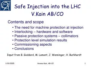
Move MSI Move MSI horizontally from B1 to B2 and shift longitudinally to get clearance of Q6 FHI, LHC IP2 inside injection
Move existing MSI magnets • Move existing MSI horizontally from B1 to B2 – OK • For clearance of Q6 need to move downstream by 194 mm/12 mrad = 16.2 m - OK • 20.1 m available between MSIA1 and Q5 • Still 3.9 m drift between MSI and Q5 for eg. vacuum equipment and maybe shielding (limited aperture at MSI losses at injection) • Can TI 2 deliver the beam? • Existing MSI magnets impose a change in vertical trajectory through Q5 • Problem is aperture in Q5, presently inj beam is 21 mm displaced wrt orbiting beam; 11.1 mm vertical beam stay clear NEW Q5 needed if MSI kept • MKI might need to be moved to recover vertical angle together with Q5 • Trajectory matching in horizontal plane aggravated by wrong Q5 kick • Very likely not feasible even with newly designed Q5 FHI, LHC IP2 inside injection
Option 2 Move redesigned MSI FHI, LHC IP2 inside injection
TI2 geometry MBIB Green: LHC ring Blue: present TI 2 Magenta: proposed TI 2 FHI, LHC IP2 inside injection
Q6 FHI, LHC IP2 inside injection
MKI and MSI FHI, LHC IP2 inside injection
New MSI design, moved Matched at Q5 and MKI FHI, LHC IP2 inside injection
New MSI design, moved Vertically same trajectory as now FHI, LHC IP2 inside injection
Thinner ‘blade’ 40 mm beam separation 20 mm beam separation FHI, LHC IP2 inside injection
Move redesigned MSI • New MSI design: • requires smaller ‘blade’ due to smaller vertical displacement between beams from long. Shift • From 40 mm to 20 mm beam separation • No change for Q5 trajectory • No change for TI 2 trajectory FHI, LHC IP2 inside injection
Option 2 Mirror injection FHI, LHC IP2 inside injection
Mirror injection Keep same longitudinal position no changes downstream of MSI FHI, LHC IP2 inside injection
Use existing MSI magnets Tilt existing MSI by 180 deg and redesign vacuum chamber of injected beam Roll existing MSI by 180 deg Chamber should be here! FHI, LHC IP2 inside injection
S-shape in MSI straight Q6 – TI 2 collision even with extremely strong bends FHI, LHC IP2 inside injection
Use UJ22 and cross before Q8 FHI, LHC IP2 inside injection
Use UJ22 and cross before Q8 MBIBs 3 x stronger than present ones FHI, LHC IP2 inside injection
Use UJ22 and cross before Q8 Still no sufficient vertical separation at H-crossing FHI, LHC IP2 inside injection
Conclusions • Option 1 – Move existing MSI • Move MSI transversely onto the other beam and long. closer to Q5 • With existing MSI magnets seems not feasible • Option 2 – Move redesigned MSI • Smaller beam separation requires thinner blade (40 20 mm) • If septum design possible least impact on overall injection region • Option 3 – Mirror injection • Tilt MSI by 180 deg and mirror the injection to the inside of the ring • Existing MSI can only be used if vacuum chamber can be modified (invert horizontal angle) • TI 2 needs to pass below the ring and bend the beam back into the MSI aperture (S-shape) • Crossing inside MSI straight impossible with reasonable bending radii • UJ22 and Q8 crossing: requires tremendously strong bends or change of tunnel geometry; to be further studied • For all options MKI modifications to be checked FHI, LHC IP2 inside injection
MBIB data sheet FHI, LHC IP2 inside injection