Download
1 / 25
250 likes | 416 Views
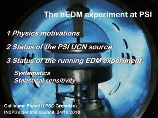
The 3 He Injection Test for the nEDM Experiment. 10/2008. Xiaofeng Zhu D. Dutta, H. Gao, M. Busch, Q. Ye, T. Mestler, X. Qian, W. Zheng Duke University nEDM collaboration. Outline. Introduction Experimental setup Experimental procedure 3 He injection/collection

E N D
The 3He Injection Test for the nEDM Experiment 10/2008 Xiaofeng Zhu D. Dutta, H. Gao, M. Busch, Q. Ye,T. Mestler, X. Qian, W. Zheng Duke University nEDM collaboration
Outline • Introduction • Experimental setup • Experimental procedure • 3He injection/collection • Polarization measurement • Summary
Neutron EDM • A permanent EDM dn • The current upper limit : dn<2.9x10⁻²⁶e•cm Phys. Rev. Lett. 97, 131801 (2006) • Improve sensitivity by 2 orders of magnitude • A mixture of ultra-cold neutrons in superfluid 4He, and polarized 3He Physics Report 237, 1 (1994) • T and CP violation • Physics beyond SM • Baryon Asymmetry of Universe - + d•E s = 1/2
Why Polarized 3He? n 3He B E B E - s = 1/2 + • Extract n precession frequency using spin dependant nuclear reaction • Co-magnetometer dn dipole moment d3He =0
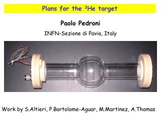
3He T1 measurement in d-TPB coated acrylic cell filled with superfluid 4He H. Gao, R. Golub, P. Huffman, Q. Ye, and others at TUNL Preparation for injection test Collect polarized 3He in a pyrex cell filled with superfluid 4He Demonstrate polarization loss is acceptable R&D Efforts on 3He at TUNL
Setup for 3He Injection Test Dilution Refrigerator Atomic Beam Source: ~100% polarized 3He 1014 atoms/s Liquid He tank at 4K Solenoid magnet Tri-coilmagnet Cryostat With 4K 50K shield
Injection/Collection • Collection volume pre-filled with superfluid 4He • 4He Temp. at 0.3~0.5K • 4He Volume~27cc • 3He flux from ABS • Intensity:1014 atoms/s, • Velocity~100m/s • After ~100s, ~10163He atoms are expected in superfluid 4He
To ABS at room temp. Helium gas Filling pipe Helium bath vessel 50K 4k Heat exchanger 1.3k 0.7k 0.24k Film burner Pyrex cell Dilution refrigerator Helium @0.35k tricoil
Cool the pyrex cell to 0.35K • Thermal Link : OFHC copper foil • DR cooling power: 13.8mW with mixing chamber at 0.24K To ABS DR 1K pot Cs ring Filling pipe for L-He Copper foil to cool the cell Measurement cell @.35K DR MX at 0.24K
nEDM collaboration meeting superfluid film suppression • Active method • Film burner • Passive method (optional) • Cs ring • Non wetting of He on Cs surface • Safety issues
Spin Rotation • During injection, 3He travel through a curved magnetic field . • At ABS exit, 3He spins parallel to B field • Solenoid coil (20G) • Axial field along ABS axis • Tri-coil system (20G) • Vertically down direction • Due to space limitation • During injection, spins rotate by 45 deg. Solenoid coil 45 45o Tri-coil
Spin Rotation: Polarization Loss Negligible • Spin follows the field direction • AFP condition: • Monte-carlo simulation: • Average spin rotation ~ 3.35±0.30 deg • Polarization ~98.8% • Low vapor density to suppress collisions 3He trajectory Non AFP AFP
Polarization Measurement with 10143He/cc • Measurement at high field ~1kG to increase signal size • Pulsed NMR with a single transceiver coil • Less sensitive to thermal displacement • Smaller RF power • Better signal/noise ratio expected than that of AFP
Field Homogeneity for pNMR • T*2 related to longitudinal field gradient: • The block time of pNMR is ~20μs • Transverse spin relaxation time T*2>200 μs • Averaged within 4He liquid ( R<2.5cm,|z|<2cm) • At 1.2kG, Field homogeneity needs to be < 27.5 ppm/cm (30mG/cm) Phy. Rev. A , 37 2877
Tri-coil Design and Test R • Starting with improved Helmholtz coils • 2nd and 4th order cancellation: • I2/I1=0.53146; H/R=0.76005 • By B. Filippone, Caltech • TOSCA Optimization • By S. Balascuta, ASU • Numerical and analytical calculation • T*2~2.59ms • Average over the liquid He volume, by T.Mestler, Yale • T*2~0.430ms • Consider wire geometry, by W. Zheng, Duke • Tri-coil built , axial field uniformity is ~16ppm (<27.5ppm) I1 H I2 I1 Rev. Sci. Instr. V73, 2175
pNMR for Injection Test ~1X10¹⁴ polarized protons/cc • pNMR setup at Duke • An existing magnet modified for this test: • 1kG • Uniformity ~ 80mG/cm • Tank circuit tuned ~ 3.89MHz • Proton FID signal is observed at room temperature • Comparable to 3He density during injection test Tank circuit Tank circuit magnet magnet Tecmag Apollo console
Spin tipping angle at room temp. RF duration time Spin echo signal For calibration purpose Cryogenic pre-amplifer , RF shielding, etc Trying to improve S/N on 1H FID signal T2 measurement on water sample
Faraday cage Two tunable capacitor Resonant coil Copper enclosure@1.3K Semi-rigid coax Center: Ag coated BeCu Dielectric: teflon Sheath: BeCu From D. G. Crabb, UVA Cryogenic pNMR system Faraday cage
Summary • Magnets are ready, to be assembled with cryostat • pNMR system under optimization • Injection test will be carried out at LANL
Acknowledgement • Los Alamos National Laboratory • U.S. Department of Energy under contract # DE-FG02-03ER41231 • Collaborating institutions • ASU, BU, Caltech, Duke, LANL, MIT, MSU, NCSU
Heat load to DR mix:~ 5mW 13.8mW cooling power @0.24K By T. Ito ~2.5mW from film burner By G. Seidel 0.5mW pNMR and support 1.1mW gas introduction tube Cs ring to slow down superfluid flow rate Torch to chase Cs vapor Dry ice to condense Cs effectively CsN3 test will continue Sealing test undergoing Pyrex to copper adapter 15 thermal cycles After fail and try, kapton gasket seals well with copper flange Cryogenics Cs ring Made by dry ice Epoxy 2850GT Kapton gasket
Siphon pipe to fill LHe into tricoil can Pipe for safety venting Heat rate: 2 kW/m2 Pressure drop: 5.5 psi Gas density@50K,1atm By J. Long Venting velocity: 97m/s 1.375” ID, 45” length Reynold number: 5.7x10⁵ resistant coefficient: 0.49 Rupture disc@4K Avoiding Taconis resonance Safety II: boil off of LHe within Tricoil can Siphon pipe Vacuum vent pipe
Injection test cell cooling power ~36 ~22 ~111 ~15 Injection test collection volume 4He DR Mixing Chamber nEDM collaboration meeting
nEDM collaboration meeting Injection test vs nEDM injection