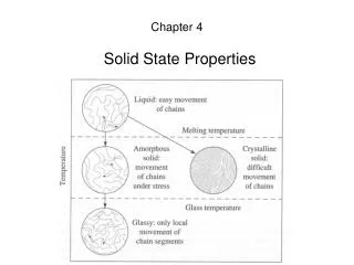
Download
1 / 46
460 likes | 463 Views
This review covers the principles of operation, design techniques, and measurement methods for high performing solid state detectors, including strip detectors and new technologies. It also discusses environmental design considerations and the use of position sensors.

E N D
Solid State Detectors- 3 T. Bowcock
1 Position Sensors 2 Principles of Operation of Solid State Detectors 3 Techniques for High Performance Operation 4 Environmental Design 5 Measurement of time 6 New Detector Technologies Schedule
Techniques for High Performance Operation • Strip Detectors • Design and Fabrication Issues • What to avoid!
Review... • In the p-strip in n-bulk (“p-in-n”) detectors • Vdep=100V • Energy to create electron hole pair is • 3.6eV ( not 1.1eV-why? ) • Average energy lost/mm • 39keV (108eh/ mm) -V Al Si + -
Drift • Electric field in Depleted region linear • 300mm detector • at 100V E=3.0keV/cm • Diffusion/Drift by multiple collisions • Takes 7ns for e’s, 20ns for holes Higher diffusion at low temps!
Ballistic Deficit Charge lost is known as the ballistic deficit Collection time
Strip Pitch and Readout Pitch and resolution • Select it: d Single strip has d/12 d/10
Choosing the Pitch • Why not make it infinitely small • transverse diffusion • 10-20 microns • construction • readout electronics! • Readout pitch • not necessarily the same as diode pitch (cost$$$) 75mm readout (25mm diode)
Intermediate Strips • Work by capacitive coupling • induced current/charge is that seen by the electrons and holes (not a post-facto charge sharing!) • Why no broader strips ? • Interstrip capacitance <1pF Need field map!
Intermediate Strips? • Loose signal • An option if • limited by resources • little noise in electronics (slow e’s) • Optimal choice is • readout each strip • pitch and width evaluated by FEA • pitch between 20 microns and 100 microns
Performance 50 mm with intermediate strip 25mm readout
Resolution • Test your resolution • series of particles of known position • testbeam telescope • cosmic telescope • longwavelength laser
Checking Resolution Optical fiber • Tests • laser • problems? • transparancy • cosmics • slower • testbeam • expensive • labour intensive Focus to 5 mm 1064nm Si transparent
Two Track Resolution • Reconstruction position as a function of proximity of one track to another
Occupancy • Best to reduce occupancy • 1% considered the benchmark • 10% too high • Reduce the length of strips • usually about 6cm • reduce to 1cm for example
AC Coupling Revisited • e=0.34pF/cm • 200nm oxide • 10pF/cm • Greater than Interstrip capacitance • Electronics at ground!
Double Sided • Needs AC coupling! • Correlation of signals • Strips can run opposite directions • 2D style r/o -V - - - - + + + + 0V
Double Sided Detector • Would like electronics at one end • Can get correlated measurement (E) giving x/y measurement • Reduces fakes • Punchthrough
Double Metal • Add another routing layer • more processing via • Expense can double • Built in stresses in SiO2 can warp Si wafer badly
Double Metal Can also use to route on single sided detectors
Example of Double Metal Detectors • LHCb prototypes
Bond Pads • Structure you will often see Typically 80 by 200 microns
n-strip detectors • We can make single sided n-strip detectors (note depletion!)
Field Plates • MOS structures
p-stops • Individual p-stops
Operating Voltage • High (overvoltage is desirable) • 250V • reduced ballistic deficit • BUT • introduces very high field regions? • Avalanche will set in if field exceeds 30V/m
Electric Field Sample field map
Guard Rings • Reduce fields at edge
Micro-Discharges • Discharges may be seen as in increase in the noise with voltage
Si Choices • Resistivity • n-type • p-strips • n-strips • double sided • p-type • Crystal orientation
Benchmark measures • Charge Collection Efficiency • Partial Depletion • Ballistic Deficit
Fabrication • Control of all steps critical • Of special interest • resistor values • implantation • oxide quality for breakdown • quality of lithography
Quality Assurance • Job of the physicist is to measure all the key parameters of the detectors • IV and CV • interstrip capacitance • resistor values • lightspot response
F/E Electronics • Binary vs Analog • Amplifier Characteristics • rise time and falltime • undershoot • Digital Performance • pipeline & logic • Noise
Noise • Hybrid is often a source of noise • bad grounding for electronics • bad grounding for supplies to detector • sensor,analog and digital all connected • The detector, f/e electronics and the hybrid should be regarded as one unit or MODULE
Material Budget • Ideally should be as low as possible • avoid high mass materials • gold • Good detector about 1% of a radiation length
Offline Analysis • Can give improvement in resolution w L R Only true if charge uniform and if the width of the cluster matches the strip width In general we have a Gaussian distribution of width determined by the diffusion coefficient (for normal incidence) d x
Offline • Corrections for the angle of the track and the known (measured) charge sharing can give great improvement • 20 to 30% in the case of 25 microns pitch detectors • Good software must accompany good hardware • Removal of deltas
7 things to avoid • Picking the wrong technology • Picking the wrong manufacturer($) • Not enough Quality Control • Bad design limiting operation • Noise in system • Treating sensor and hybrid separately • Bad analysis
Summary • We have all the elements now to think about real detectors in real environments • design issues • noise problems • See how we design a detector for LHCb