Download

1 / 44
480 likes | 584 Views
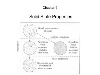
Solid State Detectors-2. T. Bowcock. 1 Position Sensors 2 Principles of Operation of Solid State Detectors 3 Techniques for High Performance Operation 4 Environmental Design 5 Measurement of time 6 New Detector Technologies. Schedule. Why use a Solid State Detector?.

E N D
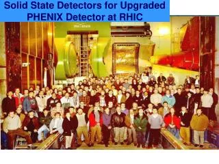
Solid State Detectors-2 T. Bowcock
1 Position Sensors 2 Principles of Operation of Solid State Detectors 3 Techniques for High Performance Operation 4 Environmental Design 5 Measurement of time 6 New Detector Technologies Schedule
Why use a Solid State Detector? • Physics requires • high rate capability • rare processes imply huge event rates • high efficiency and low dead time • good signal./noise ratio • good resolution • electronics r/o • high speed
B-physics • Detecting vertices ...
Silicon Properties • Electron-hole production at few eV • compare with 30eV in gas • Density reduces deltas • remember bubble chamber photos(!) • 100 e-h pairs/micron • solid • easy to install close to interaction point
Silicon • Properties of Si • Crystal structure • Group IV • 4 electrons in valence shell • 2D representation
Ionisation and holes e- • 1.1eV • Holes • F=mhdv/dt • In semiconductors electrical conduction takes place via two modes of electron motion. Can be viewed as motion of e-’s with charge -q and effective mass m*e and holes, +q, m*h • Intrinsic semiconductors +
Valence and Conduction Bands • In intrinsic semiconductors (no impurities) conduction band E=Ec E Ef E=Ev valence band
Thermal Properties • In intrinsic semiconductor • Note that in intrinsic semiconductors n=p=intrinsic carrier density • For Si (at room temp) ni=1.5*1010 Nc=3*1019 Nv=1*1019
Carriers properties • Carrier mobility m=v/E • 1300 cm2/Vs for e’s • 500 cm2/Vs for holes • Resistivity • reflects the doping level
Intrinsic Silicon cont’d • At room temp in a 300 micron thick detector with an area of 1cm2 total free carriers would be about 109 • cool (lower T) • can be done but cryogenics are bulky and expensive • reverse biased diode operation
Impurities III h • Group III (e.g. B) • acceptor type atoms • majority carriers=holes • p-type • Group V (e.g. P) • donor type atoms • majority carrier=e’s • n-type V e
Impurities • Do not lead to net charge! • Donor concentration Nd • Acceptor concentration Na • simplifies if impurities >> ni
Band Structure • Doped silicon conduction band E=Ec Ed (n-type) E Ea (p-type) E=Ev valence band
+ - - + - + + - - + + - - - - - - - - + + + + + + + + + + + + + + + + + + + + + + + + + + + + + + + + + + - - - - - - - - - - - - - + + + + + + - - - - - - - - - - - - - + + + + + + - - - - - - - - - - - - - + + + + + + - - - - - - + - - + - - - - - - - + + + + + + + + + + + + + + + + + + + + + + + + + + + + - - - - - - - - - - - - - - - - - - - - - - - - - - - - pn-Junction • Abrupt junction • diffusion + - - +
- + + - + + + - - - + + + - - - + + + - - - + + + - - - + - - + - - - - - - - + + + + + + + + + + + + + + + + + + + + + + + + + + + + - - - - - - - - - - - - - - - - - - - - - - - - - - - - pn-junction donor p-type n-type + - - + acceptor Space charge Carrrier density Field and potential
Diode Behaviour • Built in potential • Calculate depletion width (neutral) • Use 1D Poisson Eq.
Depletion Depth • Problem: Prove • Conversely applying a potential increases depletion width • Reverse biased diode • Note dependence on doping
Depletion Region as a Detector • Build a p+n diode • Na=1015 • Nd=1013 • At 50-100V bias voltage get 300 micron depletion in the n-part (bulk) and < 1 micron in the heavily doped part.
Depletion region • In the depletion region continual thermal generation of eh pairs • leakage current • depends on volume • Ionisation will also create pairs that will also drift and be collected • signal/noise
Fabrication • Key to use of Si is the processing • Photolithography Photoresist forms a layer a few microns thick in 30s Organic Photoresist usually “spun” on
Patterning • Photoresist exposed using a “mask” • Mask contains the design and is produced with e-beam lithography • feature size down to 0.25microns • Negative or Positive
Etching • Negative Process • Chemical etch • exposed part unaffected by etch 1 • Exposed pattern may be removed later • second etch
Example: • Aluminium line
Simple Strip Detector • Oxide passivation • Windows • Doping • B • As • Al Metallization • Al patterning • Rear Contact Al SiO2 p+ n+
2D strips Al Si
Wafer Main detector Test structures
Pulse Height Landau Distribution
Signal Shape • Simulation • charges follow e-field • Ramo’s Theorem • Finite element • Matches data
Strip Pitch • Strip pitch is the dominant factor in determining resolution Typically 40-100 microns (why not smaller) Resolution better than about pitch/4 (why?)
Charge Sharing • Charged shared (see Ramo’s Theorem!) between strips Pulse height c x
Pulse on p-strip detector -V Al Si + -
Electronics • VLSI • ASIC bonds
Electronic Noise • Noise sources • coupling of strips to each other an back plane (extra load and signal loss) • intrinsic to amplifier • ENC = a +bC • d may vary from 100-1000 depending on speed • b varies from 20 to 100 depending on speed • Sources from • leakage current • load resisitor
Signal/Noise • Electronics • speed • intrinsic characteristics • Thickness of detector and Vbias • MIPS • Capacitance of Strips • resistors • Desire about 10/1 S/N
AC Coupled Devices • Avoid draining bulk current into electronics • Usual detector built • Higher cost
Biasing Techniques • FOXFET • Reachthrough • Polysilicon resisitor • 1-10M poly Al bias strip
+++++++++ + + + + - - - - - - - - - - - - Double Sided Detectors • Using the Ohmic side • divide up the “plane” p-stops
Pixel Detectors • Pixel detectors are identical in principal to strip detectors • shape of pads smaller • few microns or 10’s of microns compared with strips of 6cm or so, • more diffiucult to route out • expensive bump bonded electronics • low capacitance(noise) • intrinsically 2D rather than 1D
Charge Coupled Devices • Very high precision (0.2microns) • Moves charge in a potential well • 2D device • Slow
CCD • Use small low capacity elements and exchange information <10e noise • Matrix of potential wells created “cell” n-doping p-type
Summary • Have seen the basics of how a strip/pixel detector works • capable of adequate S/N • only cost effective for last 10 years with advent of second generation fabrication • easily modifiable geometry • Next: high performance operation