Download

1 / 37
380 likes | 417 Views
Explore the principles of solid state detectors, focusing on the design considerations for operation in hostile environments. Learn about radiation damage, technology options, and environmental factors affecting detector performance. This insightful guide covers topics such as radiation effects, material choices, and heat management strategies for high-performance operation.

E N D
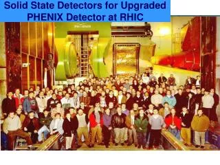
Solid State Detectors- 4 T. Bowcock
1 Position Sensors 2 Principles of Operation of Solid State Detectors 3 Techniques for High Performance Operation 4 Environmental Design 5 Measurement of time 6 New Detector Technologies Schedule
Environmental Design • Design depends on environment the detector is to operate in and the physics • Many applications • Space Physics • Heavy Ions/Nuclear physics • High Energy Physics
Example • Choose a “hostile” environment • LHCb detector
32 2 B-hadron production CP effects 10K events About 11012 BB produced/year (108 Gen. 1)
Vertex Detector • Precision tracking that: • identification of B vertices • measurement of lifetime (40fs) Bs Ds K
series of 17 1/2 disks Geometry Detectors separated 6cm during injection small overlap Positioning and movement to 5mm 10cm
Dose after 1yr 1014 station 6 1 MeV equivalent neutrons/cm2 1013 1 2 3 4 5 6 Radiation Environment • Including effects of walls, vessel • High doses at tips • (1/r2) cm
Radiation Damage in Si • Large amounts of radiation (neutron or MIP) introduces defects into the crystal • More acceptors • material switches to being p-type • Neff=Nd-Na
n-strip detectors Neff=Nd-Na
Radiation Damaged n-strip • Depletion starts from side with strips • We can run the detector underdepleted • Full depletion voltage rises…guess • Many other effects are important
Radiation Damage • Damage increases the numbers of states in the band gap conduction band E Ea (p-type) E=Ev valence band Distribution of energies and properties
Trapping • In particular the effect of some of these defects is to introduce traps for the charge carriers in the depleted zone • The traps have lifetimes that increase(from ns to ms) with radiation dose and affect the pulse shape/diffusion
Ballistic Deficit Simulation-1D
Picking the Technology • n-strips or p-strips?
Technology Options for LHCb Vertex Detector procon p stripSingle sided processingRapidly falling efficiency Reduced cost (30%)and ease of handling below partial depletion Minimum pitch 12 m High field region on opposite surface to readout Thin detectors advantageous for Needs to be thinner for given multiple scattering operating voltage.(Lower signal) Handling(cost) of thin detectors. n strip High efficiency at partial depletion gives Lithographic processing of back lower operating voltage and lower power (Cost and handling) High field region (after irradiation) at Minimum pitch 40m. readout strips. Operating partially depleted at tip still allows full depletion (high CCE) elsewhere. bothMaterialDifficult to handle Charge Correlation Offset voltages on one side of detector for electronics. Thermal contact - sensitive face? Prototype 1998 Comparison of Technology
n-strip prototypes • design
Source Tests Ru source adc counts
Thickness • Physics • Signal • Bias voltage • depending on technology • Current
Irradiated Detectors (V. Prelim) Irradiation at 3*1014 Irradiated (200V) unirradiated
Temperature • Important operating condition • leakage currents • defects dynamics are strongly temperature dependent • colder is not always better • Heat Management • electronics • ohmic heating in the detector
0 -4 Temperature at Tip (°C) -8 0 50 100 150 200 250 300 W/mm2 Module Design LHCbUK Thermal Runaway LHCb thick detectors Single Sided r and module Thermal Model: hold cooling at -10°C
Other factors • Vacuum • Inaccessibilty • Replacement
Summary • To design the detector you have to understand the environment • design the detector around the requirements • Radiation damage one of the key factors in modern experiments