Download
1 / 39
400 likes | 636 Views
Superconducting Undulator (SCU) Development at ANL. Efim Gluskin on behalf of the APS/ANL team Superconducting Undulator R&D Review Jan. 31, 2014. Outline. Developments of the APS superconducting undulator SCU design and performance - cryogenic design and performance

E N D
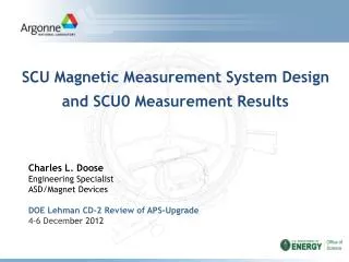
Superconducting Undulator (SCU)Development at ANL Efim Gluskin on behalf of the APS/ANL team Superconducting Undulator R&D Review Jan. 31, 2014
Outline • Developments of the APS superconducting undulator • SCU design and performance - cryogenic design and performance - magnetic measurements and SCU performance - integration at the APS storage ring - reliability and spectral performance • Future developments • R&D for the LCLS-II SCU prototype
SCU performance comparison Brightness Tuning Curves (SCUs1.6 cm vs. UA 3.3 cm vs. Revolver U2.3 cm & U2.5 cm) • Tuning curves for odd harmonics of the SCU and the “Advanced SCU” (ASCU) versus planar permanent magnet hybrid undulators for 150 mA beam current. • The SCU 1.6 cm surpasses the U2.5 cm by a factor of ~ 5.3 at 60 keV and ~ 10 at 100 keV. • The tuning range for the ASCU assumes a factor of two enhancement in the magnetic field compared to today’s value – 9.0 keV can be reached in the first harmonic instead of 18.6 keV.
First SC undulators for the APS APS superconducting undulator specifications SCU0 and SCU1 spectral tuning curves
Main milestones of the ANL part of the project • Design of the NbTiundulator magnet • Design of the cryostat for both 1.5 m undulators • Design of the vacuum system • Procurement of undulator cores, cryostat, cryocoolers, vacuum components • Assembly and test of cryogenic and vacuum systems for NbTiundulator • Magnetic measurements of the NbTiundulator • Assembly, test and magnetic measurements of the Nb3Sn undulator Total duration of the project: 18 months
Current direction in coil Period • + • • + • + • + • + e- • + • + • + • + • + • pole coil Superconducting planar undulator topology Current directions in a planar undulator Planar undulator winding scheme Magnetic structure layout On-axis field in a planar undulator Cooling tube Beam chamber
SCU0 Assembly • SCU0 was assembled at the APS in a new SCU facility • Several sub-systems were first assembled including cold mass and current lead blocks • Current lead assemblies were tested in a dedicated cryostat before installation into the SCU0 cryostat • LHe tank with He circuits were leak checked • Several fit tests were done • SCU0 assembly was completed in May 2012 SCU0 being assembled in the new facility Fully assembled cold mass Cold mass and current lead assemblies fit test
Winding SCU coils up to 2.5 m long Vacuum epoxy impregnation Curing Oven 4 m cryostat 2 m cryostat SCU magnetic measurement system Cryogenic and magnetic Testing
He fill/vent turret Cryostat vacuum vessel Cryocooler Cryocooler Current leads Beam chamber flange Cryocooler Vacuum pump Cryocooler SCU0 cryostat
He fill/vent turret SC magnet LHe vessel LHe piping 20 K radiation shield 60 K radiation shield Beam chamber Beam chamber thermal link to cryocooler SCU0 design • SCU0 Design Conceptual Points: • Cooling power is provided by four cryocoolers • Beam chamber is thermally insulated from superconducting coils and is kept at 12-20 K • Superconducting coils are indirectly cooled by LHe flowing through the channels inside the coil cores • LHe is contained in a 100-liter buffer tank which with the LHe piping and the cores makes a closed circuit cooled by two cryocoolers • Two other cryocoolers are used to cool the beam chamber that is heated by the electron beam SCU0 structure
He recondenser flange LHe vessel (StSteel/Cu bimetal ) Cold mass base frame Flexible Cu braids SC magnet Beam chamber Cu bar Flexible Cu braids SCU cold mass
SCU0 cryo-performance • Designed for operation at 500 A, SCU0 operates reliably at 650 A-680 A. • The magnet cores remain at 4 K even with 16 W of beam power on the beam chamber • No loss of He was observed in the period • of 12-month The measured temperatures in the SCU0 cryostat at beam current of 100 mA (24 bunches), SCU0 magnet is off.
SCU0 Cold Test – Cryogenic Performance: Cool down • A design concept of cooling the undulator down with compact cryocoolers has been confirmed. The system achieved cool-down during a day, using cryocooler power alone The temperatures of the 4-K cryocoolers during initial cool-down of SCU0. The cryocoolers are 2-stage devices, with the 1st stage providing shield cooling and the 2nd stage cooling the liquid helium reservoir and superconducting magnet.
SCU magnetic measurement system design: Mechanical overview • One 3.5 m travel linear stage • Three ±1 cm travel transverse linear stages • Three manual vertical stages • Two rotary stages • Warm Ti tubing installed inside cold Al beam chamber as guide for carbon fiber Hall probe assembly
Warm guiding tube approach Warm (~300K) carbon fiber tube holding Hall probe /coils Warm (~300K) Ti guiding tube Cold (20K) Al beam chamber - Estimated heat load on cold beam chamber in this configuration is 1 W. - The beam chamber is cooled by two cryocoolers with cooling capacity of 40 W @ 20 K.
SCU magnet measurement system • SCU horizontal measurement system was built at the APS. The concept is based on a warm-bore system developed at the Budker Nuclear Physics Institute for superconducting wigglers. • The measurement system includes • Scanning Hall probe: • Three-sensor rotatable Hall probe • Stretched wire coils: • Rectangular, delta and figure-8 coils. • Longitudinal stage linear travel : 3.5 m; positioning accuracy: 1 micron. • Transverse stage linear travel: 1.0 cm.
SCU magnetic measurement Hall sensor assembly Three Arepoc Hall sensors and one temperature sensor mounted to a ceramic holder which is then installed in a carbon fiber tube Two sensors measure By above and below the mid-plane separated by ~1mm. Third sensor measures Bx. The assembly was calibrated from room to LHetemperature. By2 By1 3.8 mm OD 29 mm length Bx
SCU0 magnetic measurement resultsHall probe data, trajectory and phase errors Trajectory Phase errors 0.73 degrms No magnetic tuning
SCU0 on the APS storage ring SCU0 design, fabrication, magnetic measurements, testing: 2010-2012 SCU0 installed: December 2012. Completed detailed commissioning plan during extended machine startup: January 2013 (~130 hr). SCU0 released for User operation: January 29, 2013
Chamber alignment 2 3 4 5 6 sensor 0 1 core 7 8 • Chamber alignment critical to protect SCU0 from excessive beam-induced heat loads. • Alignment corrected for cool-down. • Beam-based alignment using ID steering and ΔT, giving 100-μm accuracy. • Alignment is stable over time.
Thermal analysis of beam-induced heat load 2 3 4 5 6 sensor 0 1 core 7 8 • Analytical image-current heat load modeled using ANSYS. • Modeled chamber temperatures are within 10% of the measured temperatures. • Results are very satisfying, in light of 2-to-10-fold underestimated heat loads at ESRF, MAX (in-vac).
Predicted vs. Measured chamber temps & power chamber heater calibration thermal model Al length 1.33 m Added Al and both SS sections * Image-current heat load only; does not include 0.25 W synchrotron radiation heat load. 19
Next SCUs for APS Upgrade • The APS Upgrade program includes two types of SCU: • SCU1: a 1-m long magnet in 2-m long SCU0-type cryostat • SCU2: a 2.0−2.3-m long magnet in 3-m long cryostat • Currently the SCU1 is under construction and planned for the installation on the APS ring in December 2014
Main milestones of the ANL part of the project • Design of the NbTiundulator magnet • Design of the cryostat for both 1.5 m undulators • Design of the vacuum system • Procurement of undulator cores, cryostat, cryocoolers, vacuum components • Assembly and test of cryogenic and vacuum systems for NbTiundulator • Magnetic measurements of the NbTiundulator • Assembly, test and magnetic measurements of the Nb3Sn undulator Total duration of the project: 18 months
Summary APS has developed, implemented and extensively tested robust cryogenic design for a planar SCU. The design employs closed loop LHe system. APS has developed and implemented magnetic measurement system that permits to characterize SCUs with the state-of-the-art accuracy and reproducibility. APS has successfully integrated SCU magnet, vacuum system and cryostat in the APS storage ring. SCUO has demonstrated superb operational record through one year of user operations Developed SCU technology is ready to be applied for the future generation of radiation sources
Hall probe data, vertical field and 1st field integral <Typical By field with Main coil current of 500A and correction coil current of 51.7A 1st field integral of above data>
SCU0 and Undulator A at the APS Sector 6 • SCU0 cryomodule has been installed in the downstream end of 6-ID on December 2012
Mechanical vibration 1 2 3 Integrated power density (μm rms), from 2 Hz to 100 Hz Amplitude at 8.375 Hz (mm rms) • Cryocoolervibrations do not adversely affect the beam motion. • Vibration measured at three locations: • Beam chamber, 40 cm upstream of SCU0 • Vacuum vessel, beam height • Support girder base (not shown) • Results for beam chamber shown at right.
Thermal sensors map, SCU0 chamber Transition temperatures monitored in the ring (100 mA) 6-ID SCU0 SCU0 temperatures monitored in the lab
Beam-based alignment of SCU0 chamber using thermal sensors Net resistive wall heating increases when the beam is not centered in the chamber. This can be used to find the vertical center of the chamber. Radiation from the upstream bending magnet can potentially strike the cold chamber. BPMs at the dipole are used to steer the beam and minimize the temp.** Beam steering in the dipole also shows a vertical chamber displacement, consistent with the ID beam steering.
Impact of SCU0 on beam operation • First field integral measured with beam • Variation in first field integral was inferred from effort of nearby steering correctors. • Field integrals agree reasonably well with magnetic measurements in stand-alone tests. • Effect of quench on beam • Beam motion is small, even without fast orbit feedback running, as in this example. • Quench does not cause loss of beam • Beam position limit detectors were not triggered.
Quenches Quench event induced by sudden loss of 20 mA of the stored beam Magnet temperatures were recovered quickly(2-3 min). Device has quenched during unintentional beam dumps. Procedures to mitigate these quenches are under investigation. Device is powered down prior to planned beam dumps. With the exception of beam dumps, the device quenched only twice in 8 months of user operations, operating above its 500-A design current. Stored beam was not lost, and total SCU0 downtime was < 1 hr.
SCU0 X-ray performance At 85 keV, the 0.34-m-long SCU0 produced ~45% higher photon flux than the 2.3-m-long U33. Photon flux comparisons at 85 keV. Main: Simulated and measured SCU0 photon flux . Inset: Measured photon flux for in-line U33.