Download
1 / 19
190 likes | 351 Views
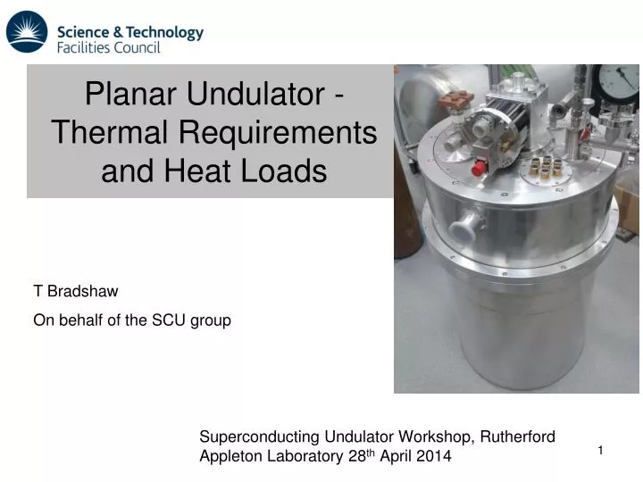
Planar Undulator - Thermal Requirements and Heat Loads. Superconducting Undulator Workshop, Rutherford Appleton Laboratory 28 th April 2014. T Bradshaw On behalf of the SCU group. Magnet Operating Point. “Load line” is for illustration only – slightly curved in reality.

E N D
Planar Undulator -Thermal Requirements and Heat Loads Superconducting Undulator Workshop, Rutherford Appleton Laboratory 28th April 2014 T Bradshaw On behalf of the SCU group
Magnet Operating Point “Load line” is for illustration only – slightly curved in reality Wire Cu:Sc ratio is 0.575:1 Need temperatures below 4K to give adequate margin for the conductor Estimations give low minimum quench energies for the magnet ~µJ which is worrying as this effects the magnet stability Note that load line is not linear as shown 2
Requirements Shield Top Magnet RT RT Bore tube Bot Magnet Shield The thermal resistances at the end of the bore tube are the bellows assemblies
Concept • Cryocoolers at ends of magnet will reduce load on 1.8K stage • Beam load 30-40W ? Beam tube cooled by two dedicated cryocoolers Wakefield heating uncertain (see later) Current leads 4K 1.8K RT 50K 12-16K Upper Magnet (1.8K) ~30-40W Lower Magnet (1.8K)
Heat load summary 4K 0.95W Magnet 93mW 55K 46.9W 16.2K 41.4W Beam tube The 1.8K system has a heat lift capacity of 200mW – size should be adequate. Beam tube could be up to 30-40W worst case (see later) Breakdown of 2K load – total 93mW ignoring any joint heating
Cryocooler operating points Coolers on beam tube Cooler on turret ...these are approximate positions There was a study on the use of cheaper 408Ds with lower cooling power – this solution was not feasible as beam tube temperature ended up too high
Wakefield Heating What we were originally working to in terms of heat loads: Image Current Heating in Diamond.doc - Duncan Scott estimates – what we originally worked to. We have been following COLDDIAG – instrument on Diamond looking specifically at wakefield heating. From Robert Voutta’s presentation at meeting on 16th January 2013
Wakefield Heating From Robert Voutta’s presentation at meeting on 16th January 2013 Note that these loads are over a 490mm length
Wakefield Heating Numbers are scary: Wiggler I15 getting 20W over full length (1820mm) Wiggler I12 getting 10W over full length (1640mm) Shamelessly taken from TD-ID-REP-081 by Ed Rial Looked at behaviour of cryocoolers and derived heat load from load map and helium pressure control Note that they have been able to reduce the spread by plotting against a parameter derived from bunch lengths etc… - this is for illustration Note that DLS wish to increase current from 300mA Also separation in wigglers is higher than the planar
Wakefield Heating • What do we do? • Suspicion is that most of the heating is not wakefield heating – it is due to small cavities that are absorbing rf • Need to ensure that the beam tube is as clean as possible • Roughness ≈ skin depth – a few microns • Transitions – Steps less than 100 microns, minimise gaps • We don’t have a good handle on the size of the heating • - have made provision for extra cryocoolers – likely discontinuities are at the ends of the beam tube which is where we have situated the cryocoolers • - have a good margin of safety on the cooling power • Need to keep following the COLDDiag and DLS measurements: Basically proportional to resistivity and inversely proportional to gap – make an attempt to scale from other results …..
Wakefield Heating The Cryogenic Permanent Magnet Undulator (CPMU) results were taken with beam tube at 147K (TDI-ID-REP-084). If we assume that the RRR of the copper used was about 100 and the wakefield heat is proportional to resistivity then the heating effect should be reduced by a factor of about 40. This seems to give anomalous results. The “adjusted for SCU” column assumes a 1/gap dependancy and for the CPMU a proportionality to resistivity. The SCU parameters are gap = 5.2mm and length = 2m. Ignore adjusted Assumes copper with an RRR=100
Wakefield Heating Different materials and different RRRs will give very different beam heating – if we are understanding the numbers….. Probably will end up gold plating – only require a few microns which is the skin depth at these frequencies
Turret Assembly System is a continuous flow cryostat with a flow of ~10mg/s
Turret details Aim is to test the turret assembly for cooling power and operation – there are some wrinkles that we need to understand. We are also testing the current leads, thermometry and thermal balances.
Turret details Turret in preparation
Cryostat Heat Loads • Cryostat uses HTS leads to limit load on 4K stage • Beam tube is assumed at 12-16K and a load of 40W from beam heating • Using 3 x Sumitomo RDK-415 coolers. One on turret and two on the beam tube
Cryostat Tests Struggling to get the correct mass flow – looking at needle valve and trap as flow restrictors
Summary • Conductor requirements are for ~2K. • MQE for the conductor is a bit worrying. • Using a continuous flow cryostat to get ~200mW (require ~100mW). • Not sure of beam/wakefield heating – allowed for worst case. Will probably need plating. • Turret works – but flow needs looking at. • Looking at thermal aspects of bath to magnet interface – test programme.