Download
1 / 24
240 likes | 348 Views
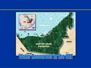
Dynamics of nutrients in the Gdańsk Gulf; numerical simulations. Fig. 1. The map of the Gdańsk Gulf with the location of sampling stations. Fig. 2a. Simulated profiles of temperature at the stations A and B.

E N D
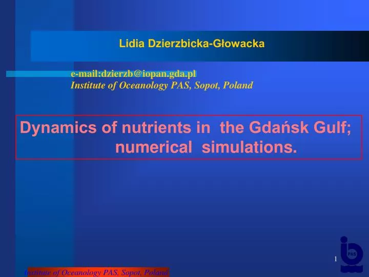
Dynamics of nutrients in the Gdańsk Gulf; numerical simulations.
Fig. 1. The map of the Gdańsk Gulf with the location of sampling stations.
Fig. 2a. Simulated profiles of temperature at the stations A and B
Fig. 2b. Simulated of surface temperature at the stations A and B
Fig. 3. Simulated profiles and observed values of total inorganic nitrogen at the stations A and B
Fig. 4. Simulated profiles and observed values of phosphate at the A and B
total inorganic nitrogen phosphate Fig. 5. Simulated and mean observed values of total inorganic nitrogen and phosphorus in the upper layer at the stations A and B Renk (2000) obtained relationship of phosphate and total inorganic nitrogen in the euphotic layer in the southern Baltic Sea as P=0.072N+0.115. This equation suggests that in the vegetation season the P:N =1:14.1. In the Gdańsk Gulf in this period the N:P=10.8; but in the Gdańsk Deep is 6.5.
Fig. 6a. Simulated profiles of phytoplankton biomass at the stations A and B
Fig. 6b. Simulated and observed values of phytoplanktonat the surface sea at the stations A and B
Fig. 7a. Simulated profiles of zooplankton biomass at the stations A and B
Fig. 7b. Simulated and observed values of depth integrated of zooplankton at the stations A and B
Fig. 8. Phytoplankton and zooplankton biomass at the stations A and B