Download
1 / 103
1.05k likes | 1.41k Views
Chapter 9. Simulation of Switching Converters. Overview. PSpice PSpice Simulations using .CIR PSpice Simulations using schematics entry PSpice Simulations Using Behavioral Modeling PSpice simulations using vendor models Small-signal analysis of switching converters

E N D
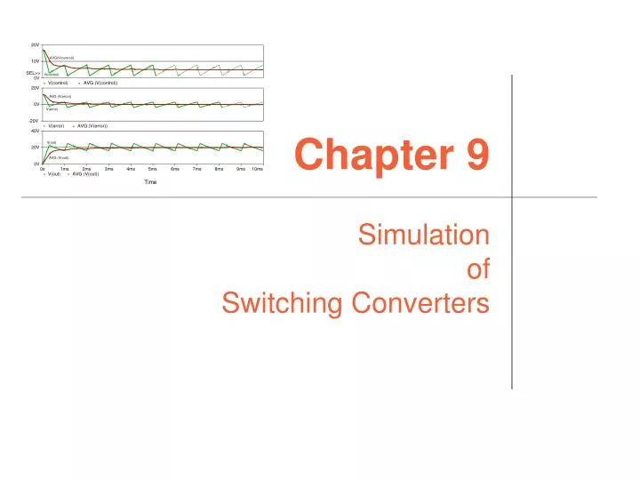
Chapter 9 Simulation of Switching Converters
Overview • PSpice • PSpice Simulations using .CIR • PSpice Simulations using schematics entry • PSpice Simulations Using Behavioral Modeling • PSpice simulations using vendor models • Small-signal analysis of switching converters • Creating capture symbols for PSpice simulation • Solving convergence problems • Matlab • Simulink Simulation of switching converters
PSpice Simulations using .CIR An Ideal Open-Loop Buck Converter Open-loop buck converter simulation * SWITCHING FREQUENCY = 1 KHZ ; DUTY CYCLE = 50% VPWM 1 0 PULSE(0 10 0 1US 1US 0.5MS 1MS) * PULSE PWM SOURCE: PULSED VOLTAGE = 10 V, RISE TIME = 1 US, * FALL TIME = 1 US, PULSE WIDTH = 500 US, PERIOD = 1 MS. L0 1 2 10M C0 2 0 100U RL 2 0 5 .TRAN 50US 20MS .OPTION ITL5=0 .PROBE .END Simulation of switching converters
PSpice Simulations using .CIR An Ideal Open-Loop Buck Converter Simulation of switching converters
PSpice Simulations using .CIR An Ideal Open-Loop Buck Converter L = 50 mH Simulation of switching converters
PSpice Simulations using .CIR An Ideal Open-Loop Buck Converter L = 5 mH Simulation of switching converters
PSpice Simulations using .CIR An Ideal Open-Loop Buck Converter L = 1.25 mH Simulation of switching converters
PSpice Simulations using .CIR An Ideal Open-Loop Buck Converter L = 10 mH and C = 500 uF Simulation of switching converters
PSpice Simulations using .CIR An Ideal Open-Loop Buck Converter L = 1.25 mH and C = 500 uF Simulation of switching converters
PSpice Simulations using .CIR Voltage-controlled switch S<name> N+ N- NC+ NC- SNAME .MODEL SNAME VSWITCH (RON=0.01 ROFF=1E+7 VON=0.7 VOFF=0) Simulation of switching converters
PSpice Simulations using .CIR Current-controlled switch W<name> N+ N- VN WNAME .MODEL WNAME ISWITCH (RON=0.01 ROFF=1E+7 ION=0.1 IOFF=0) Simulation of switching converters
PSpice Simulations using .CIR Buck Converter with an Ideal Switch OPEN-LOOP BUCK CONVERTER WITH AN IDEAL SWITCH * SWITCHING FREQUENCY = 1 KHZ ; DUTY CYCLE = 50% VS 1 0 10.0 VPWM 100 101 PULSE(0 1 0 1US 1US 500US 1MS) S1 1 2 100 101 SX RSX 100 0 10G DFW 0 2 D1 L0 2 3 10M C0 3 0 100U RL 3 0 5 .MODEL SX VSWITCH (RON=0.01 ROFF=1E+7 VON=1 VOFF=0) .MODEL D1 D .TRAN 0.05MS 20MS .PROBE .END Simulation of switching converters
PSpice Simulations using .CIR Buck Converter with an Ideal Switch Simulation of switching converters
PSpice Simulations using .CIR Buck Converter with an Ideal Switch Simulation of switching converters
PSpice Simulations using .CIR Using Initial Conditions IC L0 2 3 100U IC=1 C0 3 0 IC=5 .TRAN 2NS 200NS UIC Simulation of switching converters
PSpice Simulations using schematics entry Boost converter Simulation of switching converters
PSpice Simulations using schematics entry Simulation of switching converters
PSpice Simulations using schematics entry Simulation of switching converters
PSpice Simulations Using Behavioral Modeling • ABM.OLB part library • Control system parts Simulation of switching converters
Control system parts Simulation of switching converters
Control system parts Simulation of switching converters
Control system parts Simulation of switching converters
Control system parts Simulation of switching converters
Control system parts Simulation of switching converters
PSpice-equivalent parts Simulation of switching converters
PSpice-equivalent parts Simulation of switching converters
Operators in ABM expressions Simulation of switching converters
Operators in ABM expressions Simulation of switching converters
Functions in arithmetic expressions Simulation of switching converters
Functions in arithmetic expressions Simulation of switching converters
Examples of ABM blocks use ABM and PARAM Simulation of switching converters
Examples of ABM blocks use Node voltages can be accessed from ABM blocks Simulation of switching converters
Examples of ABM blocks use RMS meter If(argument,then,else) If (TIME<=0, 0, SQRT(SDT(PWR(V(%IN),2))/TIME)) Simulation of switching converters
Examples of ABM blocks use PWM modulator Simulation of switching converters
Examples of ABM blocks use VCO implementation with ABM1 Simulation of switching converters
PSpice Simulations Using Control Blocks PWM modulator with control blocks Simulation of switching converters
PSpice Simulations Using Control Blocks Model of an operational amplifier Simulation of switching converters
PSpice Simulations Using Control Blocks Open loop frequency response Simulation of switching converters
PSpice Simulations Using Control Blocks Closed loop amplifier Simulation of switching converters
PSpice Simulations Using Control Blocks Closed loop frequency response Simulation of switching converters
Voltage –mode PWM boost converter Simulation of switching converters
Voltage –mode PWM boost converter Simulation of switching converters
PSpice simulations using vendor models .TRAN 0 30m 0 0.1u .OPTIONS STEPGMIN .OPTIONS ABSTOL= 10p .OPTIONS ITL1= 400 .OPTIONS ITL4= 500 .OPTIONS RELTOL= 0.01 .OPTIONS VNTOL= 10u Simulation of switching converters
PSpice simulations using vendor models Simulation of switching converters
Vorperian models for PSpice Simulation of switching converters
Vorperian models for PSpice Simulation of switching converters
Vorperian models for PSpice Simulation of switching converters
Vorperian models for PSpice **** VMSSCCM **** * Small signal continuous conduction voltage mode model * Params: RMPHITE --> External ramp height * D --> Duty cycle * Ic --> Current flowing from terminal C * Vap --> Voltage across terminal A P * Rsw --> Switch on resistance * Rd --> diode on resistance * Rm --> which models the base storage effects * Re --> models ripple across esr of cap * Pins control voltage -- * common -------- | * passive----- | | * active -- | | | .subckt VMSSCCM A P C VC Params: RMPHITE=2 D=0.4 IC=1 VAP=20 + Rsw=1e-6 Rd=1e-6 Re=1e-6 Rm=1e-6 efm 4 0 value ={v(Vc)/rmphite} e2 A 6 value={v(0,4)*Vap/d} g1 A P value={v(4)*IC} gxfr 6 P VALUE={I(vms)*D} exfr 9 P VALUE={V(6,P)*D} vms 9 8 0 rd 8 C {d*rd+(1-d)*rsw+d*(1-d)*re+rm} rope 4 0 1g rgnd 0 P 1g .ends Simulation of switching converters
Small-signal analysis of switching converters Small-signal AC analysis Simulation of switching converters
Small-signal analysis of switching converters Simulation of switching converters