Download
1 / 21
210 likes | 299 Views
Overview of all superconducting splices in the LHC machine. N. Catalan Lasheras Chamonix 2010 LHC Performance Workshop 25 January 2010. Outline. Splices Inventory. Numbers and circuit criticality Stored Energy MIITs and hot spot temperature 600 A corrector circuits Brief description

E N D
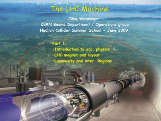
Overview of all superconducting splices in the LHC machine N. Catalan Lasheras Chamonix 2010 LHC Performance Workshop 25 January 2010
Outline • Splices Inventory. Numbers and circuit criticality • Stored Energy • MIITs and hot spot temperature • 600 A corrector circuits • Brief description • Line M and N. US welding • PCS measurements during HW Commissioning • Existing NC • Inner triplet 13 kA splices • Future • MCI • Missing studies
Superconducting splices. How many? • More than 100000 (105) splices!!
Criticality of a SC circuit • Main circuits incorporate more protection • Cold diodes • Energy Extraction • Larger bus-bar cross-section • MIITs and hot spot temperature estimated in the bus-bar according to real decay data and bus-bar section • Not a factor 104 but a factor 2 • Always safe as in nominal conditions • What about failures • In the quench detection? • In the EE switches opening? Quench of the bus-bar in adiabatic conditions. Thanks to G. Kirby
Splice types in the LHC. • Splices vary in length, copper to SC ratio, insulation, mechanical fixation • You will hear in the following talks about 13 kA and 6 kA
Line N Interconnection Ultrasonic welding
Problems with ultrasonic welding in sector 7-8. Line N. • Reported by D. Tommasini to MARIC on November 2006 after the inspection of the first installed sector • Presence of insulation between wires • Bad alignment with reduction of contact surface • Cryolab measurements showed 4 to 19 nOhms • US welding machines put in conformity • Suspected interconnections re-done during following warm-up • Test proposed during powering to spot catastrophic cases
PCS splice verification • Test systematically done during powering tests for all 600 A circuits • Current plateau at minimum current (200 A). Resistance deduced from QPS voltage measurements. • Repeated at nominal current. Data stored in MTF • Assumed resolution < 1mOhm
Results from the last powering campaign • Resistance is indeed proportional to the number of splices but noise is very high. • Noise depends on the circuit type. Cable length, number of magnets and inductance. • RCO circuit is a 120 A circuit and test is done at 100 A. RCO
Results from last hardware commissioning campaign RQ6 RCO • Expected value is between 4 and 6 nOhms • RQ6 (6xMQTL) has a higher average splice value. • Systematic. May be due to internal splices in the magnet • RCO splices are nominally higher than others
Inner triplet 13 kA splices • Two double bus-bars Cu/SC • 5 kA and 8 kA • Brazed similarly to the 6kA flat cable • All splices protected together with the magnets at a 100mV threshold
NC 948545 on a 120 A octupole corrector • As for the spool, high resistance was seen during the ElQA tests (>mOhm) • Need to open the cryostat to locate and repair the fault
Conclusions • What is the maximum credible incident (MCI) affecting each of these circuit types • Quench detection failing? Non propagating quench • Arcing in a spool piece next to M1, M2 line • ...? • Work ahead of us: • Investigation of excessive resistance in 600 A circuits • Verify the splice parameters (mainly for US magnets) • Evaluate heating of the bus-bar under accidental conditions • …