Download
1 / 46
470 likes | 610 Views
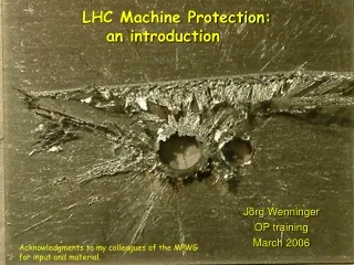
LHC Machine Protection. B. Dehning CERN AB/BI. Contend. Damage, Quench, Risk Protection Strategy Collimators Design approach Particularities of Superconducting Magnets Beam loss measurement System System settings and database Survey and tests

E N D
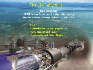
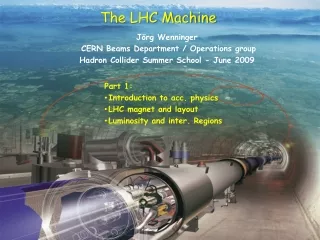
LHC Machine Protection B. Dehning CERN AB/BI BIW 2008, B.Dehning
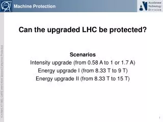
Contend • Damage, Quench, Risk • Protection Strategy • Collimators • Design approach • Particularities of Superconducting Magnets • Beam loss measurement System • System settings and database • Survey and tests • Calculation and Simulation of damage risk and false dump BIW 2008, B.Dehning
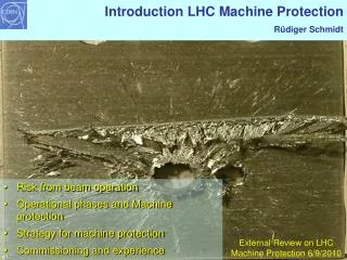
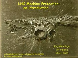
25 cm Material Damage Experiment at the SPS V.Kain et al. 6 cm • Proton beam, 450 GeV, Cu, Fe sandwich target • beam size σx/y = 1.1mm/0.6mm • 21012 no damage • 81012 damage Safe at 0.6 % of full LHC intensity BIW 2008, B.Dehning
Density Change in Target after Impact of 100 Bunches Cross sectional view copper solid state beam impact 2 dimensional hydrodynamic computer code, N.A. Tahir et al. Reduction of density by a factor 10 BIW 2008, B.Dehning
beam Magnet Quenches D. Bocian et al. cross sectional view of coil Energy deposition by the beam Temperature difference Tquench – T(steady steady case) Location of QUENCH Beams BIW 2008, B.Dehning
LOSS DURATION Ultra-fast loss Fast losses Intermediate losses Slow losses Steady state losses PROTECTION SYSTEM Passive Components + BLM (damage and quench prevention) + Quench Protection System, QPS (damage protection only) + Cryogenic System 4 turns (356 s) 10 ms 10 s 100 s Beam Loss Durations and Protection Systems Since not active protection possible for ultra-fast losses => passive system
Collimators and Absorbers Octant 7 TCT Experiment Tertiary collimators Triplet magnets Protection devices Primary collimator Secondary collimators Absorbers Tertiary halo hadronic showers • Distribution of collimators and absorbers along the ring to protect equipment against ultra-fast and up to steadystate losses Beam loss rate a. u. Primary halo particle Secondary halo + hadronic showers Beam BIW 2008, B.Dehning
Stored Beam Energies LHC will be exceptional => High RISK BIW 2008, B.Dehning
Protection Availability Safety Risk Methods: Stop of next injection Extraction of beam Reduction of operational efficiency Damage(system integrity) FailsafeRedundancy SurveyFunctional Check Quench(operational Efficiency) Design issues: Reliable components Redundancy, voting Monitoring of drifts Systems: Beam loss Monitors Quench protection system Interlocksystem ¨ Dump system Scaling: frequency of eventsxconsequence Meantime between failures 1 10-8 to 1 10-7 1/h SIL ALARP Safety System Design Approach BIW 2008, B.Dehning
Failure Rate and Checks Systems parallel + survey + functional check: • in case of system failure dump beam (failsafe) • verification of functionality: simulate measurement and comparison with expected result => as good as new BIW 2008, B.Dehning
HERA Tevatron, LHC Dump requests Dump system Interlock system The Active Protection System SOURCES of beam losses • User/operator • PC failures • Magnet failures • Collimators failures • RF failures • Obstacles • Vacuum • … BIW 2008, B.Dehning
(values proportional) DESY 2.6 – 6.6 E-03 LHC Bending Magnet Quench Levels LHC quench values are lowest BIW 2008, B.Dehning
Quench Levels and Energy Dependence • Fast decrease of quench levels between 0.45 to 2 TeV • Similar behaviour expected for damage levels BIW 2008, B.Dehning
Beam Loss Measurement System Layouts LHC BIW 2008, B.Dehning
Ionisation Chamber and Secondary Emission Monitor • Stainless steal cylinder • Parallel electrodes distance 0.5 cm • Diameter 8.9 cm • Voltage 1.5 kV • Low pass filter at the HV input Signal Ratio: IC/SEM = 60000 SEM: • Ti electrodes • Components UHV compatible • Steel vacuum fired • Detector contains 170 cm2 of NEG St707 to keep the vacuum < 10-4 mbar during 20 years IC: • Al electrodes • Length 60 cm • Ion collection time 85 us • N2 gas filling at 1.1 bar • Sensitive volume 1.5 l BIW 2008, B.Dehning
Gain Variation of SPS Chambers • 30 years of operation • Measurements done with installed electronic • Relative accuracy • Ds/s < 0.01 (for ring BLMs) • Ds/s < 0.05 (for Extr., inj. BLMs) • Gain variation only observed in high radiation areas • Consequences for LHC: • Nogain variation expected in the straight section and ARC of LHC • Variation of gain in collimation possible for ionisation chambers Test with Cs137 Total received dose: ring 0.1 to 1 kGy/year extr 0.1 to 10 MGy/year Reliable component BIW 2008, B.Dehning
Beam scanned Ionisation Chamber Simulation and Measurements Ionisation chamber response function Ionisation chamber top view M. Stockner, PhD thesis • Comparison simulation measurements Good knowledge of behaviour => Reliable component BIW 2008, B.Dehning
Ionisation chamber currents (1 litre, LHC) BIW 2008, B.Dehning
The BLM Acquisition System Real-Time Processing BEE • FPGA Altera’s Stratix EP1S40 (medium size, SRAM based) • Mezzanine card for the optical links • 3 x 2 MB SRAMs for temporary data storage • NV-RAM for system settings and threshold table storage Analog front-end FEE • Current to Frequency Converters (CFCs) • Analogue to Digital Converters (ADCs) • Tunnel FPGAs: Actel’s 54SX/A radiation tolerant. • Communication links:Gigabit Optical Links. BIW 2008, B.Dehning
Test Procedure of Analog Signal Chain Modulation Example Basic concept: Automatic test measurements in between of two fills • Modulation of high voltage supply of chambers • Check of cabling • Check of components, R- C filter • Check of chamber capacity • Check of stability of signal, pA to nA (quench level region) • Measurement of dark current • Not checked: gas gain of chamber (only once a year with source) HV ripple (pp 10 v) HV supply current HV induced signal Functional checks – Monitoring of drifts BIW 2008, B.Dehning
Secondary B Signal Primary A Signal (256 bits) (256 bits) Reception ______________ _ _ Tx Check & Signal Choice ______________ _ _ Tunnel Status Check ______________ _ _ Format Data ______________ _ _ Only CRC Only CRC Check CRC Compare Check CRC validity CRCs validity (4 byte) (4 byte) Error Error Error S/W & TTL output Signal Select Error (A or B) Status Error 10-bits Truncate extra/redundant bits (leave 160 bits) DeMux 1 2 3 … 8 Digital Transmission Line Check At the Surface FPGA: • Signal CRC-32 • Error check / detection algorithm for each of the signals received. • Comparison of the pair of signals. • Select block • Logic that chooses signal to be used • Identifies problematic areas. • Tunnel’s Status Check block • HT, Power supplies • FPGA errors • Temperature BIW 2008, B.Dehning
Detector Tunnel electronics Surface electronics Combiner Functional tests before installation Barcode check Current source test Radioactive source test HV modulation test Beam inhibit lines tests Threshold table data base comparison 10 pA test Double optical line comparison System component identity check Inspection frequency: ReceptionInstallation and yearly maintenanceBefore (each) fillParallel with beam Functional Tests OverviewPhD thesis G. Guaglio Functional checks – Monitoring of drifts
Software Overview, Management of Settings • Safety given by: • Comparison of settings at DB and front-end • Safe transmission of settings Surveyed BIW 2008, B.Dehning
Data Base Structure • Two layers • entry layer (stage tables) • validated layer (final tables) • Concept of Master and Applied table – Comparison of Threshold values (Applied < Master) • Master: less frequent changes • Applied: change of thresholds possible with user interface Failsafe BIW 2008, B.Dehning
Reliability Study – Fault-Tree Approach Relative probability of a system component being responsible for a damage to an LHC magnet in the case of a loss. Relative probability of a BLM component generating a false dump. by G. Guaglio Highest damage probability given by the Ionisation chamber (80%) because: Reduced checks Harsh environment Most false dumps initiated by analog front end (98%) because: Reduced check Quantity Harsh environment BIW 2008, B.Dehning
BLM BEAM DUMP 470 BLM connectedto each BIC (pair) Modelling of Machine Protection System S. Wagner et al.Laboratory for Safety Analysis, ETH Zurich Combined model: Fault Tree & Monte Carlo BLM Beaminterlock BIW 2008, B.Dehning
First Modelling Results Mission Distribution • fraction of early ended missions triggered by beam loss event 11.3% • false dump due to a false dump request by a component failure 1.7% contribution of the components to false dumps by triggering false dump requests. • Front electronics and BIC contribute with 40 % • BLM system analysis reveals ARC power supply contribute most to FEE failure • VME crate failure contribute significantly Comparison between simulation and installed system => survey BIW 2008, B.Dehning
Protection Availability Safety Risk Methods: Stop of next injection Extraction of beam Reduction of operational efficiency Damage(system integrity) FailsafeRedundancy SurveyFunctional Check Quench(operational Efficiency) Design issues: Reliable components Redundancy, voting Monitoring of drifts Systems: Beam loss Monitors Quench protection system Interlocksystem ¨ Dump system Scaling: frequency of eventsxconsequence Meantime between failures 1 10-8 to 1 10-7 1/h SIL ALARP Safety System Design Approach BIW 2008, B.Dehning
Literature • http://cern.ch/blm • LHC • Reliability issues, thesis, G. Guaglio • Reliability issues, R. Filippini et al., PAC 05 • Front end electronics, analog, thesis, W. Friesenbichler • Front end electronics, analog-digital, E. Effinger et al. • Digital signal treatment, thesis, C. Zamantzas • Balancing Safety and Availability for an Electronic Protection System, S. Wagner et al., to be published, ESREL 2008 BIW 2008, B.Dehning
Reserve slides BIW 2008, B.Dehning
Beam Loss Display BIW 2008, B.Dehning
Intensities • Intensity one “pilot” bunch 5⋅109 • Nominal bunch intensity 1.1⋅1011 • Batch from SPS (216/288 bunches at 450 GeV) 3⋅1013 • Nominal beam intensity with 2808 bunches 3⋅1014 • Damage level for fast losses at 450 GeV 1-2⋅1012 • Damage level for fast losses at 7 TeV 1-2⋅1010 • Quench level for fast losses at 450 GeV 2-3⋅109 • Quench level for fast losses at 7 TeV 1-2⋅106 BIW 2008, B.Dehning
Strategy for machine protection Beam Cleaning System • Definition of aperture by collimators. Powering Interlocks Fast Magnet Current change Monitor • Early detection of failures for equipment acting on beams generates dump request, possibly before the beam is affected. • Active monitoring of the beams detects abnormal beam conditions and generates beam dump requests down to a single machine turn. Beam Loss Monitors Other Beam Monitors • Reliable transmission of beam dump requests to beam dumping system. Active signal required for operation, absence of signal is considered as beam dump request and injection inhibit. Beam Interlock System • Reliable operation of beam dumping system for dump requests or internal faults, safely extract the beams onto the external dump blocks. Beam Dumping System • Passive protection by beam absorbers and collimators for specific failure cases. Beam Absorbers
Ionisation chamber SNS • Stainless steal • Coaxial design, 3 cylinder (outside for shielding) • Low pass filter at the HV input • Ar, N2 gas filling at 100 mbar over pressure • Outer inner electrode diameter 1.9 / 1.3 cm • Length 40 cm • Sensitive volume 0.1 l • Voltage 2k V • Ion collection time 72 us BIW 2008, B.Dehning
Approximation of Quench Levels (LHC) • Dump level tables are loaded in a non volatile RAM • Any curve approximation possible • Loss durations • Energy dependence Relative error kept < 20 % BIW 2008, B.Dehning
Drift times of electrons and ions (II) BIW 2008, B.Dehning
Drift times of electrons and ions (I) BIW 2008, B.Dehning
neutron proton pi+ pi- Gamma e+ e- u+ u- Response of ion chambers for different particle species Due to attenuation ofshower => increase of non linearity of chamber response BIW 2008, B.Dehning
Quench level and observation range 450 GeV 7 TeV BLMS* & BLMC Damage levels Dynamic Arc: 108 Collimator: 1013 Special & Collimator1 turn Arc 2.5 ms Quench and Damage Levels • Detection of shower particles outside the cryostat or near the collimators to determine the coil temperature increase due to particle losses BIW 2008, B.Dehning
1 bin = 5 MeV Energy [GeV] Energy spectrum of shower particles outside of cryostat • Number of charged particles and energy deposition simulated: • Energy spectrum: BIW 2008, B.Dehning
Ionisation Chamber Time Response Measurements (BOOSTER) Chamber beam response Chamber current vs beam current slength proton= 50 ns 80 % of signalin one turn Intensity discrepancy by a factor two FWHMe-= 150 ns Intensity density: - Booster 6 109 prot./cm2, two orders larger as in LHC BIW 2008, B.Dehning
Quench 7 TeV Current to Frequency Converter and Radiation Quench 7 TeV • Variation at the very low end of the dynamic range • Insignificant variations at quench levels BIW 2008, B.Dehning
LHC cycle and stored beam energy 7000 6000 energy ramp 25 MJ 360 MJ circulating beam 2808 bunches 5000 coast 360 MJ circulating beam Energy [GeV/c 4000 3000 beam dump 360 MJ via transfer line injectionphase 3 MJ 25 MJ beam transfer circulating beam 2000 1000 0 12 batches from the SPS(every 20 sec) one batch 216 / 288 bunches 3 MJ per batch -4000 -2000 0 2000 4000 time from start of injection (s) BIW 2008, B.Dehning
FNAL beam loss integrator and digitizer • Independent operation form crate CPU (FNAL, LHC) • Thresholds managed by control card over control bus (LHC combined) VME Control bus Control bus BIW 2008, B.Dehning
100 ns 100 ns to 100 s V out Threshold Comparator I + I - Reset time Integration time LHC tunnel card • Not very complicated design “simple” • Large Dynamic Range (8 orders) • Current-to-Frequency Converter (CFC) • Analogue-to-Digital Converter • Radiation tolerant (500 Gy, 5 108 p/s/cm2) • Bipolar • Customs ASICs • Triple module redundancy BIW 2008, B.Dehning
FNAL abort concentrator • Measurements and threshold are compared every 21 s (fastest) (LHC 80 s) • Channels can be masked (LHC yes) • Aborts of particular type are counted and compared to the required multiplicity value for this type (LHC: single channel will trigger abort, channel can be masked depending on beam condition) • Ring wide concentration possible (LHC no) BIW 2008, B.Dehning