Download
1 / 9
90 likes | 277 Views
Emittance Measurement Work. 08 /07/ 10 Jimmy Garland The University of Manchester The Cockcroft Institute. Emittance Measurement Work.

E N D
Emittance Measurement Work 08/07/10 Jimmy Garland The University of Manchester The Cockcroft Institute
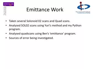
Emittance Measurement Work • Normalised transverse emittance was modeled in GPT form the gun to the end of the booster for difference initial bunch distributions from the simulated cathode. • Emittance was measured using a variety of screen based methods after the booster.
Emittance Measurement Work The nominal laser spot size on the cathode is a circle of radius 2mm. This photograph of the laser on the cathode shows a more elliptical laser spot profile. The profile is elongated in the y direction with respect to the beam line by a factor of roughly 2.
Emittance Measurement Work Emittance for a nominal circle (blue) and an ellipse (yellow and red) distribution at the cathode derived from the photo of the laser on the cathode.
Emittance Measurement Work Using a hard edged, externally generated distribution. Showing a nominal circle (blue) and ellipse of y/x ratio 2/1 (yellow and red).
Emittance Measurement Work As the ratio of the x to y transverse size increases at the cathode, the difference in emittance for x and y increases after the booster. The x emittance increases as opposed to the y due to the 90 degree rotation form the 2 solenoids.
Emittance Measurement Work Conclusions: • The measured transverse emittance agrees reasonably well with GPT simulations when using an initial cathode spot derived from the photograph of the laser on the cathode. • The laser spot size on the cathode has a large effect on the measured emittance and the difference between x and y transversely. • Striving to make the laser circular would appear to reduce the discrepancy between x and y measured emittance based on simulation.