Download
1 / 51
530 likes | 725 Views
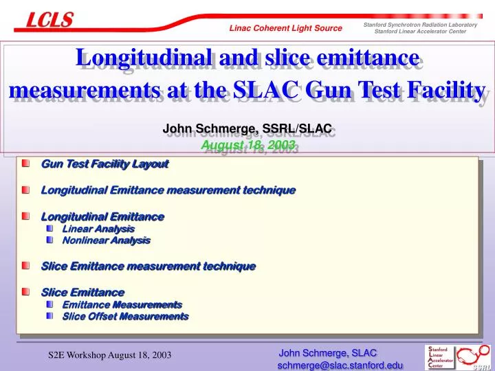
Longitudinal and slice emittance measurements at the SLAC Gun Test Facility John Schmerge, SSRL/SLAC August 18, 2003. Gun Test Facility Layout Longitudinal Emittance measurement technique Longitudinal Emittance Linear Analysis Nonlinear Analysis Slice Emittance measurement technique

E N D
Longitudinal and slice emittance measurements at the SLAC Gun Test Facility John Schmerge, SSRL/SLACAugust 18, 2003 • Gun Test Facility Layout • Longitudinal Emittance measurement technique • Longitudinal Emittance • Linear Analysis • Nonlinear Analysis • Slice Emittance measurement technique • Slice Emittance • Emittance Measurements • Slice Offset Measurements John Schmerge, SLAC
GTF Group • Paul Bolton Laser • John Castro GTF operator • Jym Clendenin Accelerator • Dave Dowell LCLS Injector Group Leader • Steve Gierman Accelerator • Cécile Limborg-Déprey Simulations • John Schmerge GTF Group Leader John Schmerge, SLAC
Experimental Goals • Transverse Emittance • en < 1.2 mm-mrad (projected) • Q = 0.2-1 nC • Longitudinal Emittance • Dt < 10 ps • sg /g < 0.1% • Laser • sjitter < 1 ps • Temporal shape – flat-top • Elaser > 100 mJ (UV) John Schmerge, SLAC
3M LINAC RF GUN DIAGNOSTIC ROOM MOD MOD MOD KLY-3 KLY-2 2 3 1 GTF LASER ROOM Gun Test Facility at SSRL DIAGNOSTICS KLY-1 8 m Laser Transport System SSRL Injector Vault GTF Control Room John Schmerge, SLAC
GTF Linac and Diagnostics Analyzing Magnet Solenoid Phosphor Screen Phosphor Faraday YAG Screen & OTR Screen Screens & Cup Quadrupole PCRF Faraday Phosphor Screen & Energy Filter Doublet Gun Cups Toroids 3m S-Band SLAC Linac John Schmerge, SLAC
GTF 1.6 cell S-band gun Laser Port Photocathode Electron Beam Exit With single crystal (100) Cu cathode “Half” Cell Full Cell John Schmerge, SLAC
GTF Beamline John Schmerge, SLAC
Laser spot used for slice emittance measurement Horizontal Projection UV Laser Image Vertical Projection counts 2 mm pixels John Schmerge, SLAC
Laser Pulse Length Streak camera resolution at 263 nm » 1 ps John Schmerge, SLAC
Longitudinal Emittance Measurement Technique analagous to quadrupole scan of transverse emittance 3 m linac (vary flinac) Quad Doublet Gun Spectrometer Energy Screen Determine Longitudinal f-Space at Linac Entrance Measure Energy Spectra vs linac phase Linear analysis allows only linear time energy correlations Nonlinear analysis allows quadratic and cubic correlations John Schmerge, SLAC
Energy Spectrum at 15 pC Time Energy John Schmerge, SLAC
Energy Spectrum at 290 pC Time Energy John Schmerge, SLAC
Linear Longitudinal Analysis Find t11, t12, t22 by fitting energy spread vs. linac phase John Schmerge, SLAC
Centroid Energy vs Linac Phase 15 pC 290 pC Least Square Error Fit Egun, Elinac and Flinac John Schmerge, SLAC
RMS Energy Spread vs Linac Phase 15 pC 290 pC Least Square Error Fit t11, t12 and t22 John Schmerge, SLAC
Linear Fit 15 pC Linac Exit Slope = -242 keV/ps Flinac =+25° keV Linac Entrance Slope = -69 keV/ps ps John Schmerge, SLAC
Linear Fit 290 pC Linac Exit Slope = -127 keV/ps Flinac = +4° keV Linac Entrance Slope = -97 keV/ps ps John Schmerge, SLAC
Linear Analysis Fit results after linac John Schmerge, SLAC
Spectrometer Resolution Longitudinal Emittance Measurements made at IQ2 = 0 A John Schmerge, SLAC
Nonlinear Longitudinal Analysis Longitudinal beam ellipse Include distortions by adding quadratic and cubic terms Ray trace to fit 5 parameters John Schmerge, SLAC
Distortions of the Longitudinal Phase Space Ellipse 20 Cubic Distortion t12 = 0 a = 0, b > 0 Quadratic Distortion t12 = 0 a > 0, b = 0 DE (keV) Undistorted Phase Space t12 = 0 a = 0, b = 0 Dt (ps) John Schmerge, SLAC
Nonlinear Fit for 15 pC as a function of Flinac calc-blue,data-red66 -6 degrees calc-blue,data-red55 0 degrees 30.5 2000 30.7 1800 30.65 30.45 1000 1600 30.6 30.4 1400 800 30.55 1200 30.35 600 30.5 1000 30.3 800 30.45 400 600 30.25 30.4 400 200 30.35 30.2 200 0 30.3 30.3 30.4 30.5 30.6 -2 -1 0 1 2 0 30.15 30.2 30.25 30.3 30.35 -2 -1 0 1 2 calc-blue,data-red81 -9 degrees 30.26 calc-blue,data-red91 -11 degrees 1600 30.1 1400 30.24 1400 1200 30.22 1200 1000 30.2 30.05 1000 30.18 800 800 30.16 600 600 30.14 30 400 400 30.12 200 200 30.1 0 30.08 0 29.95 30.12 30.14 30.16 30.18 30.2 -2 -1 0 1 2 30 30.02 30.04 30.06 30.08 -2 -1 0 1 2 Flinac = 0° Flinac = -6° Fit Spectra Measured Spectra Flinac = -9° Flinac = -11° John Schmerge, SLAC
Temporally Resolved Transverse Emittance Measurement • Introduce linear chirp • Measure beam size in dispersive section • Slice beam in energy (time) with software • Maintain chirp in the spectrometer • Small b in bend plane at quad • Large b in bend plane at quad • Quad scan in non-bend plane John Schmerge, SLAC
Quad Scan Slice Emittance Measurement Booster Quad Doublet Gun Spectrometer Energy Screen Set Booster Phase for optimum linear chirp Determine Transverse f-Space at Quad Entrance Measure Transverse Beam Size vs quad strength for different energy/time slices (typically 10 slices) John Schmerge, SLAC
Quad Scan Slice Emittance Measurement • Measure beam size as a function of quad current in a dominantly dispersive section with linearly chirped beam • Fit s11, s12, s22 • Also measure slice centroids with respect to the projected centroid • Fit x0, x0’ (centroid position and angle) • Actually 5 parameters to describe the slice ellipse not just 3 Twiss parameters John Schmerge, SLAC
Centroid Fitting xn, x’n measured with respect to the projected centroid Least Square Error routine used to determine xn, x’n John Schmerge, SLAC
Measured Beam Size and Centroids with Best Fits Q = 15 pC and Bsolenoid =1.669 kG John Schmerge, SLAC
Measured Beam Size and Centroids with Best Fits Q = 300 pC and Bsolenoid =1.982 kG John Schmerge, SLAC
Beam Images as a function of Quad Strength Horizontal Beam Size (pixels) Energy/Time Axis (pixels) John Schmerge, SLAC
Slice Image Converging beam (underfocused) Head Tail Horizontal Beam Size (pixels) High Energy Low Energy Energy/Time Axis (pixels) John Schmerge, SLAC
Head Converging beam (underfocused) Tail Horizontal Beam Size Projections (pixels) John Schmerge, SLAC
Slice Image Beam near waist Head Tail Horizontal Beam Size (pixels) High Energy Low Energy Energy/Time Axis (pixels) John Schmerge, SLAC
Head Beam near waist Tail Horizontal Beam Size Projections (pixels) John Schmerge, SLAC
Beam at the Spectrometer Screen Q = 290 pC, Flinac = + 4 ° John Schmerge, SLAC
Twiss parameters, offsets and current as function of time Q = 300 pC, Bsol = 1.937 kG John Schmerge, SLAC
Twiss parameters, offsets and current as function of time Q = 300 pC, Bsol = 1.982 kG John Schmerge, SLAC
Phase Space at Q = 300 pC Bsol = 1.937 kG Bsol = 1.982 kG John Schmerge, SLAC
Twiss parameters, offsets and current as function of time Q = 15 pC, Bsol = 1.609 kG John Schmerge, SLAC
Twiss parameters, offsets and current as function of time Q = 15 pC, Bsol = 1.669 kG John Schmerge, SLAC
Phase Space at Q = 15 pC B solenoid = 1.609 kG B solenoid = 1.669 kG John Schmerge, SLAC
Measured and Reconstructed Projected Emittance John Schmerge, SLAC
Slice Emittance John Schmerge, SLAC
Reconstructed Projected Emittance John Schmerge, SLAC
Sources of Time Dependent Kicks • Transverse Wakefields • Linac • Normal Incidence Mirror • Gun • RF kicks • Gun Exit • Linac Entrance • Linac Exit • RF couplers • Laser • Alignment • Time-Space correlation John Schmerge, SLAC
Xoffset vs Z for Q = 15 pC and Bsol = 1.669 kG John Schmerge, SLAC
Xoffset vs Z for Q = 300 pC and Bsol = 1.982 kG John Schmerge, SLAC
Time Dependent Angle in the linac for different Charges John Schmerge, SLAC
Transverse Wakefield due to Linac Misalignment x offset in 3-m structure = 1 mm, q = 300 pC, Ipk 120 A x’ vs z xmax 35 mrad x vs z xmax 20 mm Courtesy of P. Emma John Schmerge, SLAC
Back Propagate Linac Wakefield Simulation • Simulated Linac Wake produces • X0 = -20 mm at linac exit • X’0 = -35 mrad at linac exit • Back propagate output conditions and assume no wakefield to see where the beams intersect • X = 0 at z = 50 cm from linac exit John Schmerge, SLAC
Slice Intersection Points 15 pC 300 pC John Schmerge, SLAC